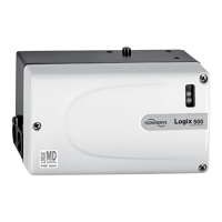
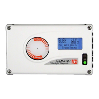
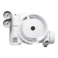
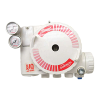
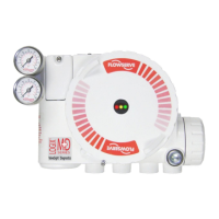
Logix
®
520MD+ and 510+ Digital Positioners FCD LGENIM0105-15-AQ – 05/16
2
6 Tubing 24
6.1 Determine Air Action 24
6.2 Connect Supply Port 25
6.3 Purging Single Acting Actuators 25
6.4 Vented Design 25
7 Electrical Connections 27
7.1 Electrical Terminals 27
7.2 Command Input (4-20 Ma) Connection 27
7.3 Multi-Function Card (AO, DO, DI) 29
7.4 V To I Card Connections 31
7.5 Limit Switches 32
7.6 Remote Mount 33
7.7 Connections For Intrinsically Safe Operation 33
8 Startup 34
8.1 Quick Start Instructions 34
8.2 Local User Interface Overview 34
8.3 Configuration Switch Settings 35
8.4 Stroke Calibration 36
8.5 Analog Output (AO) Calibration 37
9 Positioner Functions (No Display Required) 38
9.1 Live Manual Tuning (Adjusting The Gain) 38
9.2 Local Control Of Valve Position 38
9.3 Command Source Reset 38
9.4 Factory Reset 38
9.5 Viewing Version Numbers 38
9.6 Analog Input Calibration 39
9.7 Select And Calibrate Analog Output 39
9.8 Select Discrete Output 39
10 Positioner Functions (LCD Display) 40
10.1 Main Display View 40
10.2 Menu Overview 42
10.3 Menu Features 43
11 Hart Communication 49
11.1 Valvesight DTM 49
11.2 Hart 375/475 Handheld Communicator 49
11.3 Changing Hart Versions 49
11.4 Burst Mode 50
12 Model Features 51
12.1 MD+ Positioner Diagnostic Levels 51
12.2 Valvesight DTM Diagnostic Levels 51
13 Multi-Function Card 52
13.1 Analog Output (AO) 52
13.2 Discrete Output (DO) 52
13.3 Discrete Input (DI) 52
14 V To I Card 53
15 Limit Switches 53
15.1 Limit Switch Operation 53
15.2 Limit Switch Types 53
Contents
1 General Information 5
1.1 Using This Document 5
1.2 Terms Concerning Safety 5
1.3 Protective Clothing 5
1.4 Qualified Personnel 5
1.5 Valve And Actuator Variations 5
1.6 Spare Parts 5
1.7 Service / Repair 6
1.8 Disposal 6
1.9 Basic Operation 6
1.10 Hart 6
1.11 Position Definition 6
1.12 Command Input And Final Command 7
1.13 Outer Loop 7
1.14 Inner Loop 7
1.15 Detailed Sequence Of Positioner Operations 8
1.16 Inner Loop Offset 8
2 Specifications 10
2.1 Input Signal 10
2.2 Pneumatic Output 10
2.3 Air Supply 10
2.4 Analog Output – Multi-Function Card 10
2.5 Stroke Output 11
2.6 Remote Mount Specifications 11
2.7 Limit Switch Specifications 11
2.8 V To I Board Specifications 11
2.9 Positioner Performance Characteristics 11
2.10 Physical Specifications 11
2.11 Temperature 11
2.12 Valvesight DTM Software Specifications 12
3 Hazardous Area Certifications 13
4 Storage And Unpacking 14
4.1 Storage 14
4.2 Unpacking 14
4.3 Pre-Installation Inspection 14
4.4 Labels 14
5 Mounting And Installing 15
5.1 Mounting To Mark One Linear Valves 15
5.2 Mounting To Flowtop Linear Valves 16
5.3 Mounting To Standard Valtek Rotary Valves 18
5.4 Mounting To Maxflo Rotary Valves 20
5.5 Mounting To Rotary Namur (Automax) Valves 21
5.6 Mounting To A Linear Namur Pneumatic Actuator 23
 Loading...
