Valtek GS General Service Valve FCD VLENIM0300-00-A4 08/14
16
Turn the hex nut (113) from the bellows seal assembly
(6) counter clockwise to loosen, remove the seal car-
rier (91) and profile ring (60) then move the bellows
seal assembly down and out.
NOTICE
The bolting between plug and stem
are secured against twisting. Type A
and B bellows seal assemblies are secured with a lock
bushing (8).
12. Use the Packing Driver Tool (See Section 16: Special Tools)
to remove the packing (88) and the packing box ring (93).
13. Use a standard brass scraper or other suitable tool to
remove all old gasket material; then clean the gasket
surfaces.
NOTICE
Examine the valve trim and bon-
net components. If the nominal and
actual values differ by more than 5% a control valve
overhaul may be required.
14. Check stressed surface areas for damage such as
scoring or deformities.
15. Use a standard brass scraper or other suitable tool
to clean all bolting. Check for corrosion or any other
damage.
Reassembly of the valve with a Bellows Seal
Bonnet Assembly:
16. Lubricate all bolt and screw threads and bearing sur-
faces (stem, plug, underside of the nuts) with a suit-
able, approved lubricant (See Section 15: Lubricants).
NOTICE
Never allow lubricants to come in
contact with the bonnet or sealing
surfaces.
17. Install and finger tighten a new profile ring (55) and
seat ring (20).
18. Insert the Seat Change Tool (See Section 16: Special
Tools) into the body of the valve and turn clockwise
using a suitable torque wrench (See Section 14: Re-
quired Torque, for screwed seats).
19. Lower the plug (50) into a three jaw-chuck with soft
brackets and install a new lock bushing (8) into the
plug (Type A and B).
NOTICE
The cone of the lock bushing must
open to the top.
1
108
55
58
20
50
8
40
114
59
6
59
42
48
7
93
88
87
109
80
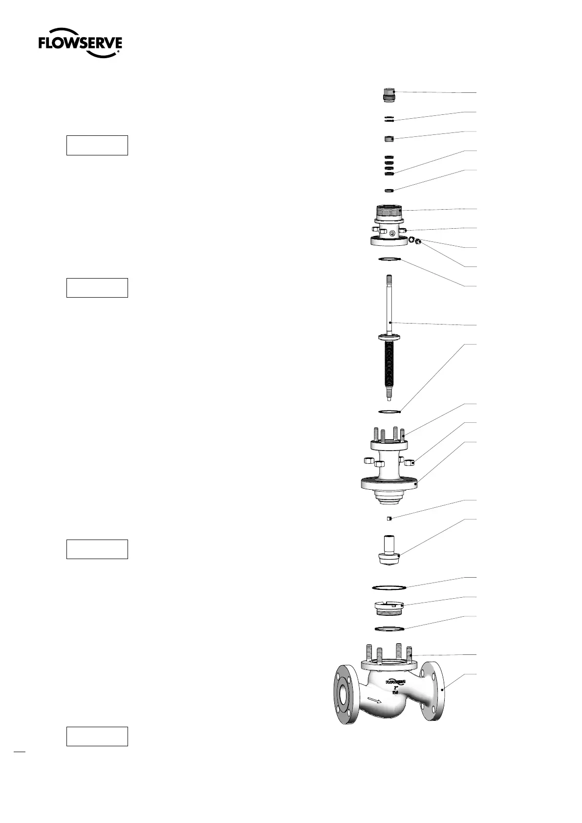
Figure 10: Disassemble / Reassemble the valve with bellows seal assembly
for type A designs (Valve parts see Table 13, Page 17)