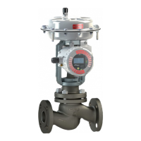
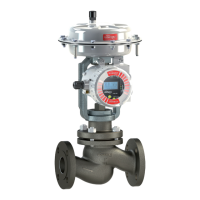
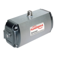
1-7
Flowserve Corporation, Valtek Control Products, Tel. USA 801 489 8611
O
S
O
S
E0032
NOTE: Step 9 applies only to valves with pneumatic
actuators. If an electric or hydraulic actuator is
used, return the plug to the midstroke position and
proceed to tighten.
CAUTION: Failure to return the plug to a
midstroke position (electric or hydraulic opera-
tors only) will cause damage to the actuator
and / or the valve during the bonnet tightening
sequence. This is due to the inability of most
electric / hydraulic actuators to accommodate
the
1
/16 inch / 1.60 mm back-drive during the
tightening sequence.
9. For air-to-close valves, skip this step and go to step
10. For air-to-open valves, check for proper plug
seating as follows: When proper seating occurs,
the bonnet flange will be forced up against the
finger-tight body bolting with such force that it will be
impossible to move the flange. If proper seating
does not occur, the bonnet flange can be wiggled
with light hand force. Should this occur, place air
under the actuator piston and retract the actuator to
approximate midstroke position. Turn the plug out
of the actuator plug stem one additional thread and
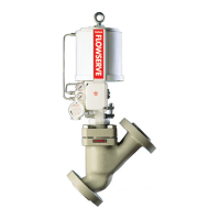
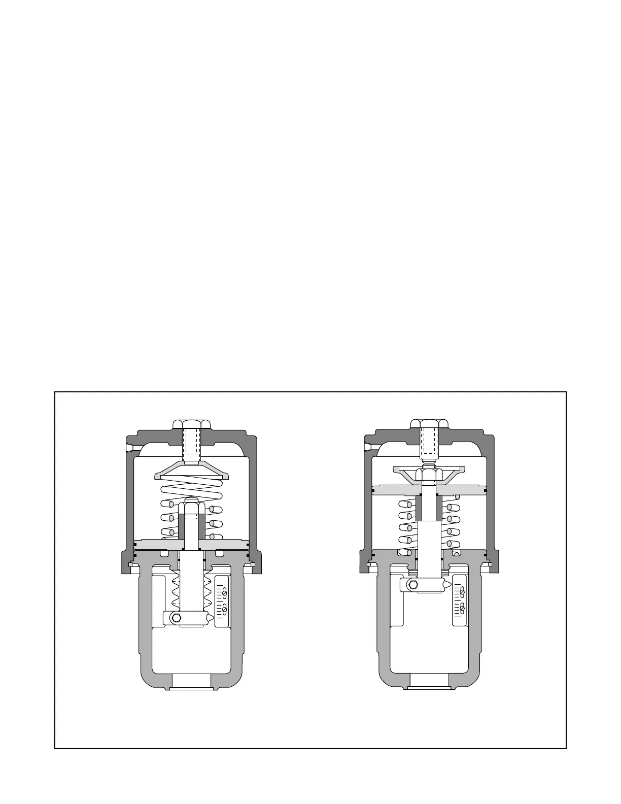
Figure 3: Air-action Configurations
repeat above seating procedure. When the bonnet
flange becomes tight against the finger-tight body
bolting, the plug is properly seated. If necessary,
repeat above procedure until proper seating occurs.
10. Move the plug to the extended (or closed) position
for pneumatic actuators and to the midstroke posi-
tion for electric, hydraulic or mechanical actuators.
Begin tightening the bonnet flange bolting in a
manner that will keep the bonnet flange square /
parallel with the body. Tighten the first bolt
1
/6 turn,
then tighten the bolt directly opposite
1
/6 turn and so
on around the flange. Firmly tighten all bolts evenly
and completely to compress the bonnet gasket and
to seat the bonnet. Torque the bonnet bolts to the
suggested torque values in Table III.
11. Apply air over the piston to seat the plug. For all
throttling valves, adjust the stem clamp so that with
full instrument signal to the positioner the full signal
scribe line on the positioner cam points to the center
of the cam roller bearing.
NOTE: For on / off valves, the bottom of the stem
clamp should simply be lined up with the bottom of
actuator stem (plus or minus
1
/
16
inch / 1.60 mm).
Air-to-Open Air-to-Close