Fault Codes
The following table gives the meanings of all fault codes used on the digital controller:
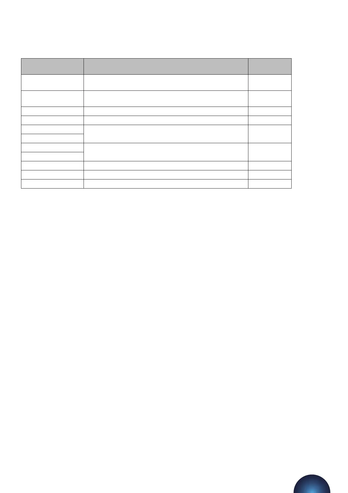
Fault Code Description Auto/Manual
Reset
LOW PRESSURE The system pressure is below the [LOW PRESSURE] set point.
User Defined
HIGH PRESSURE The system pressure is above the [HIGH PRESSURE] set point.
User Defined
LOW H20 The break-tank low level float switch has been activated Auto Reset
HIGH H20 The break-tank high level float switch has been activated Auto Reset
P1 FAIL The controller has detected a fault (incorrect current draw) on
the respective pump Manual Reset
P2 FAIL
P1 FLOOD LIMIT The respective pump has run for longer than the [FLOOD
LIMIT] period Manual Reset
P2 FLOOD LIMIT
ERR. 1 The signal from the pressure sensor is out of range Manual Reset
EXCESSIVE DEMAND There have been 4 pump starts within an 8 hour period Manual Reset
SERVICE The pressurisation unit is due an annual service Manual Reset
For practical guidance on diagnosing and rectifying faults, please refer to the Troubleshooting section of this
manual.
Shutdown procedure
The pressurisation unit must be shut-down during any of the following scenarios:
• Work is being carried out on the system.
• Work is being carried out on the pressurisation unit
• The heating/cooling system is being flushed
To shut down the pressurisation unit, please follow the steps below:
1. Isolate the electrical power supply to the pressurisation unit
2. Isolate the mains water supply to the pressurisation unit
3. Isolate the pressurisation unit from the system using the internal isolation valve
4. If it is anticipated that the unit will be out of commission for more than 24 hours, it is advisable to drain
the water from the break tank.
Start-up Procedure
Aention – This procedure is for restarting the unit aer being shutdown (as described above). For initial start-
up and commissioning procedures, please refer to the Commissioning section of this manual.
To restart the pressurisation unit, please follow the steps below:
1. Perform a visual inspection of the unit and installation to check for signs of damage
2. Check the break-tank for debris/deposits and remove if necessary
3. Turn on the mains water supply to the pressurisation unit and allow the break tank to fill
4. Open the internal isolation valve
5. Turn on the mains power supply and wait for the controller to start
6. Depending on the conditions in the system, the unit may display one or more fault codes at this point.
Maintenance
Due to variations in operating conditions, and the varying loads placed on pressurisation units, it is not feasible
to provide accurate predictions of component lifespan. The most eective method of maintenance is to
inspect the pressurisation unit for early signs of component failure and take action accordingly.
The following maintenance procedures should be performed at least once a year:
flowpress WMDA Pressurisation Units
23