Earth/Ground Tester
Setup
9
R
A
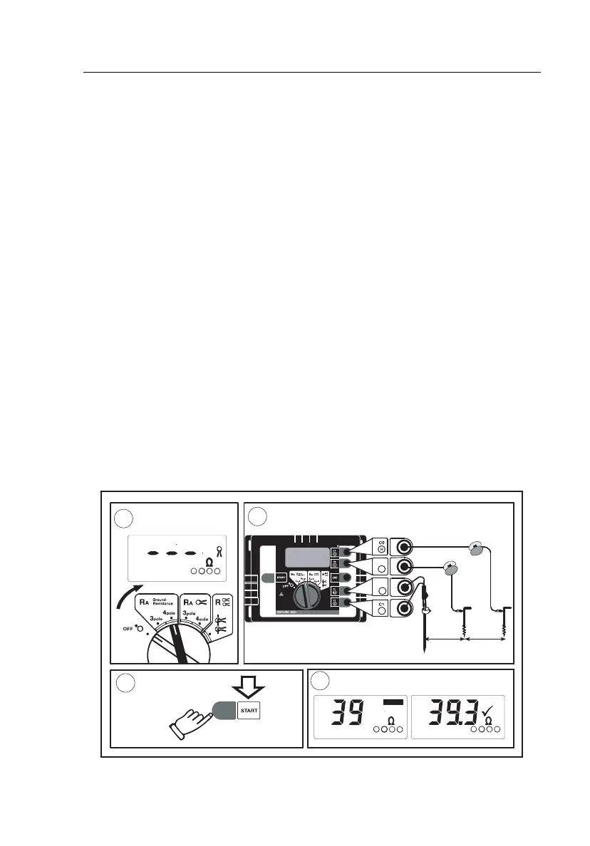
4-pole Measurements
Refer to Figure 5.
A Select function R
A
4-pole.
Display as shown below.
B Connect test leads.
Connect terminals E/C1 and ES/P1 to the earth system to be
measured with the 2 supplied test leads (1.5 m). Place 2 ground
stakes in earth/dirt. Minimum distance between earth electrode
(E/C1), probe (S/P2), and auxiliary earth (H/C2) should be at least
20 m! The ES test lead eliminates the influence of the test leads.
Connect the stakes with the 25 m and 50 m cable reels to H/C2 and
S/P2 as shown below.
C Press START.
The “active” symbol indicates that a measurement is in progress. For
a continuous measurement keep START pressed.
D The symbol “9” indicates a completed measurement. The result is
kept on the display until a new measurement is started or the rotary
switch is turned.
m 02>
m 02>
SESE
H
evitca
E
HS
SE
2P/S
2C/H
1P/SE
1C/E
sulp
V
05
xa
m
2P
S
1P
SE
E
E
HS
SE
FLUKE
1
2
3
4
FLUKE 1623
Earth/Ground Tester
edv004.eps
Figure 5. R
A
4-pole Measurements
Shop for Fluke products online at:
1.877.766.5412
www.MyFlukeStore.com