30
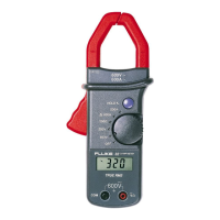
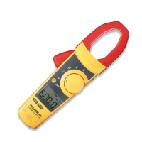
Clamp Meter
2
Required Equipment
Table 1 lists the equipment required to perform the calibration procedure.
Table 1. Calibration Equipment
Instrument Type Recommended Model
AC Calibrator Fluke 5700A
Transconductance Amplifier Fluke 5220A
Digital Multimeter Fluke 77
Lab Supply (0-10V)
Resistor (MF, 30.1 ohms, 1%) Fluke PN 296665
Resistor (MF, 27.4 ohms, 1%) Fluke PN 296368
50 Turn Current Coil 5500A coil
Preparing for Calibration
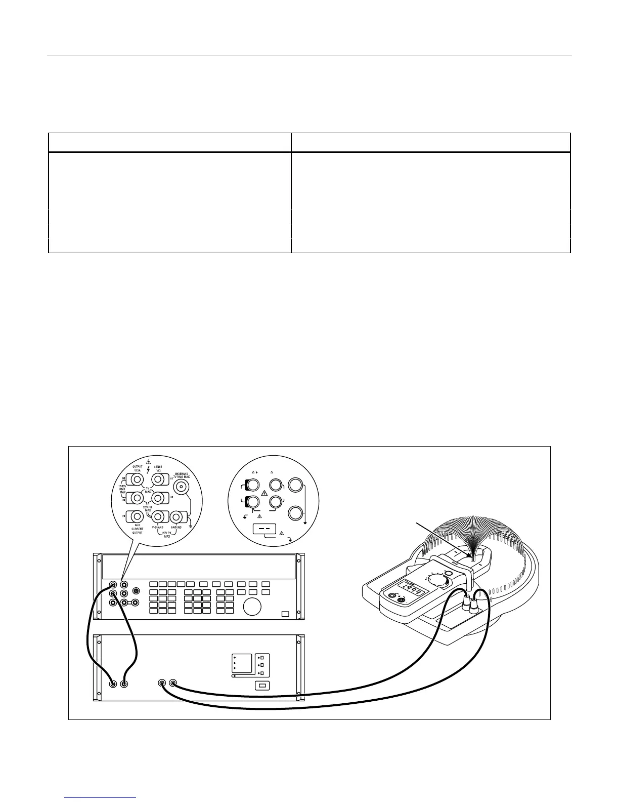
1. Configure the test equipment as shown in Figure 1.
2. Disassemble the meter by removing the four screws on the case back.
3. Remove the battery cover and front panel.
4. Turn on the meter and use a DMM to verify that the battery level is between 7 and 9 volts. If the battery
does not meet this criteria, replace the battery before proceeding with the calibration procedure.
Note
The test equipment should be allowed to warmup and stabilize for at least 30 minutes before
starting the calibration checks.
Calibrator
5700A/5720A 5500A
5220A
5500A Coil
20V PK
MAX
HI
LO
TC
TRIG
OUT
1000V
RMS
MAX
20V
RMS
MAX
1V PK
MAX
20V PK
MAX
NORMAL AUX
SCOPE
V, ,
RTD
A, -SENSE,
AUX V
200V PK
MAX
Conductor
H
HOLD
200A
400A
200V
OFF
200
600V
600V
COM
V
rq2f.eps
Figure 1. Calibration Equipment Configuration