Calibration Adjustments
3
Calibration Adjustments
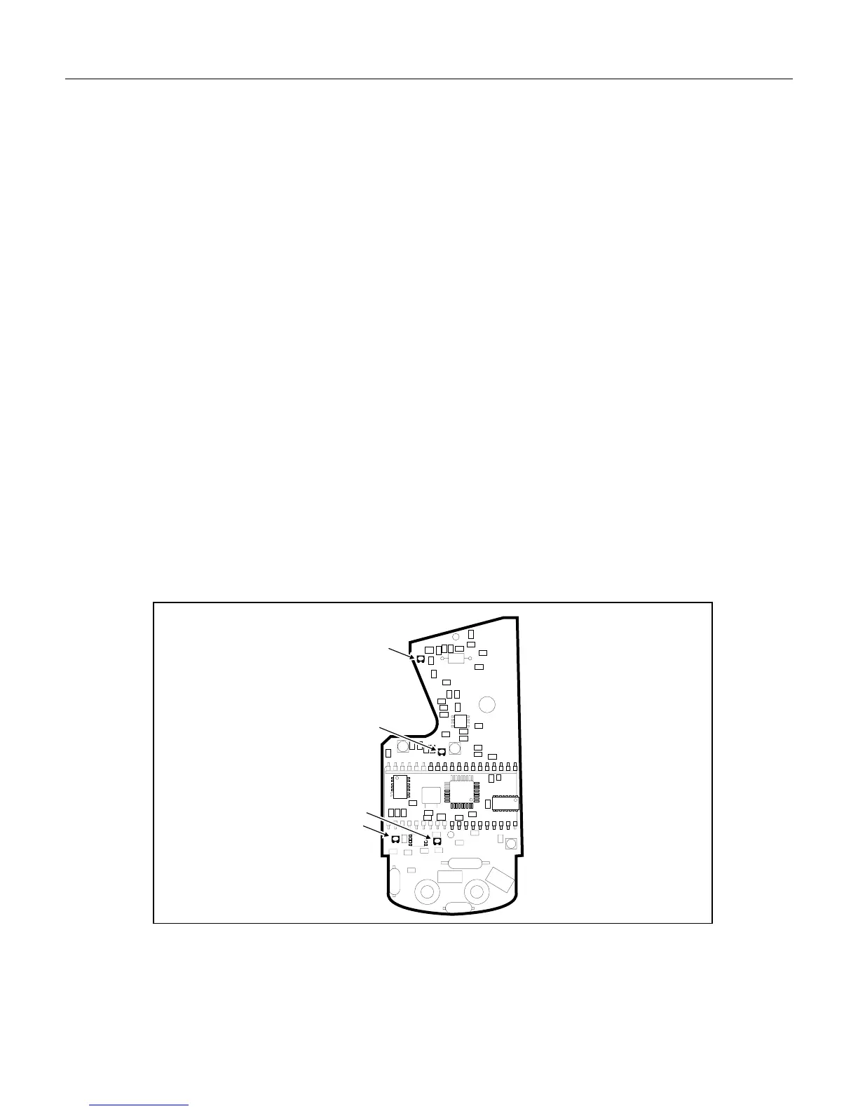
Complete the following procedure to calibrate the meter. Refer to Figure 2 for the adjustment locations.
AC Voltage Calibration
1. Set the meter to the 200V AC range. Connect the calibrator to the input of the meter, and program the
calibrator to 100V AC at 60 Hz. Adjust VR3 to indicate “100.0” on the display.
2. Set the calibrator to 0V and set the meter to the 600V AC range. Set the calibrator to 600V AC at
60 Hz, and verify that the display reading is within the tolerance specified in Table 2.
AC Current Calibration
1. Set the calibrator to 3.8 amps at 60 Hz.
2. Set the meter to the 200A AC range. Clamp the meter around the 5500A coil as shown in Figure 1.
Center the jaws on the coil using the indicator marks on the jaws of the meter and adjust VR2 to
indicate “191.0” on the display (adjusting to 191.0 amps ensures that the clamp meets accuracy
specifications where response roll-off occurs).
3. Set the meter to the 400A AC range and set the calibrator to 7A AC at 50 Hz. Verify that the display
reading is within the tolerance specified in Table 2. If the value is out of tolerance, balance the
calibration between the 200A and 400A ranges so that both ranges fall within the tolerance specified in
Table 2.
Ohms Calibration
The ohms ranges are not adjustable.
Continuity Beeper Calibration
Connect a 30.1e resistor across the meter’s input terminals, and turn VR4 slowly until the beeper sounds.
VR2
VR3
VR4
VR1
VR2
VR3
VR1
VR4
rq3f.eps
Figure 2. Calibration Adjustment Locations
Low Battery Indication Calibration
1. Disconnect the battery from the meter, and connect the lab supply to the battery terminals. Set the
power supply to 6.7V, and turn on the meter. Slowly adjust VR1 until the low battery indicator
appears.