30
Clamp Meter
4
2. Set the power supply to 7.0V, and verify that the low battery indicator goes off.
Reassembly
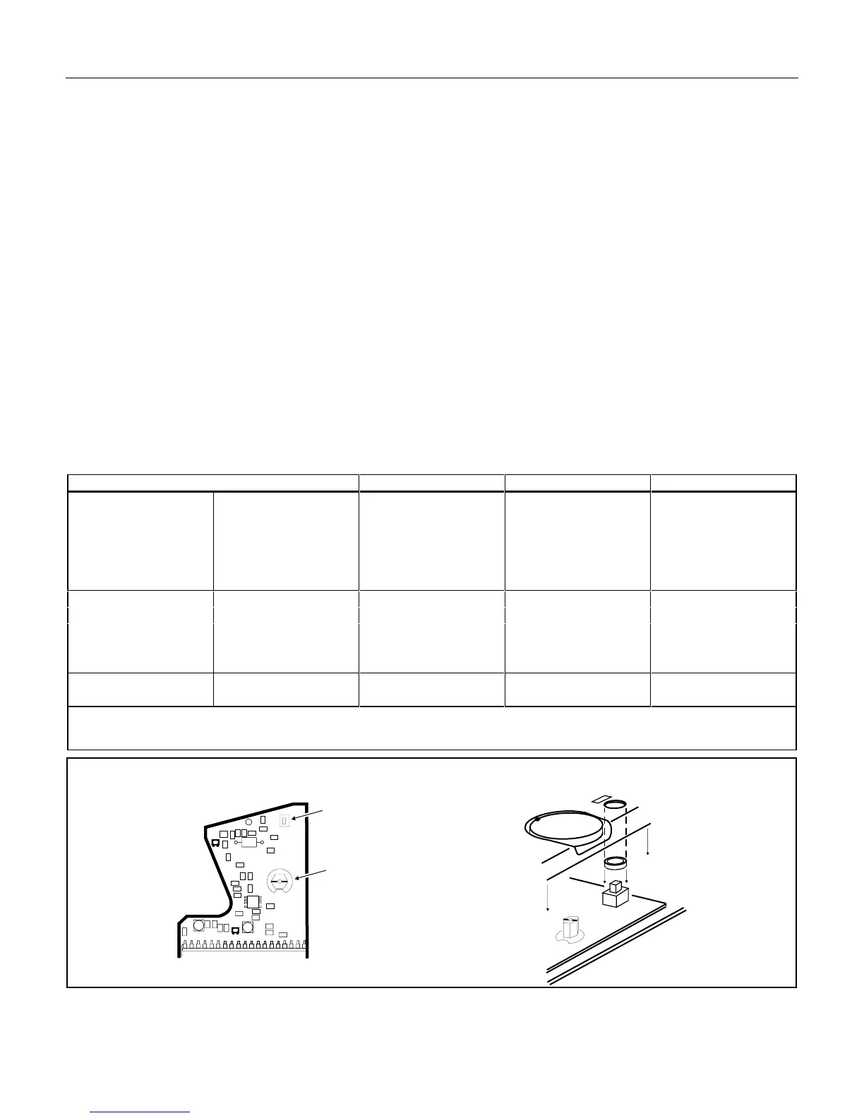
1. Press and release the hold switch (so the switch is down), and fit the button over the switch housing.
2. Set the mark on the function switch axis to the 200V AC position (horizontal position), see Figure 4.
3. Set the rotary switch on the front panel to the 200V position.
4. Reinstall the front panel, making sure the wires surrounding the PCB are not caught between the front
and back case halves.
5. Reinstall all but the battery cover screw (three screws) on the case back.
6. Reinstall the battery and battery cover. Then secure with the battery cover screw.
Performance Check
To perform a performance check on the meter, set up the test equipment as shown in Figure 1. Referring to
Table 2, set the 5700A calibrator controls as shown, and verify that the meter readings fall between the high
and low limits for each range.
Table 2. Performance Test Measurement Points
5700 Settings Range Low Limit High Limit
Current AC Freq. Hz
20A 60 200A 18.8A 21.2A
190A 60 200A 187.3A 192.7A
40A 60 400A 36A 44A
350A 50 400A 342A 358A
400A 60 400A 388A 412A
Volts AC Freq. Hz
20V 60 200V 19.5 20.5
190V 60 200V 187.4V 192.6V
60V 60 600V 56V 64
600V 60 600V 590V 610V
Resistance Ω
190Ω NA Ohms 186.9Ω 193.1Ω
To verify the continuity beeper, connect a 27.4Ω resistor (PN 296368) across the input terminals and verify the beeper
sounds.
VR2
VR3
VR2
VR3
VR2
VR3
HOLD SWITCH
FUNCTION SWITCH
HOLD
H
200V
rq4f.eps
Figure 4. Rotary Switch Position