365
Calibration Manual
8
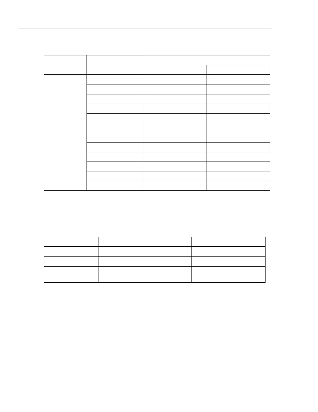
Table 2. Performance Tests (cont.)
UUT Meter Reading Limit
Test
(Switch Position)
Calibrator Output
Low High
.5A @ 50 HZ 9.6 A 10.4 A
5 A @ 50 HZ 98.7 A 101.3 A
9.5 A @ 50 HZ 187.5 A 192.5 A
.5 A @ 400 HZ 9.6 A 10.4 A
5 A @ 400 HZ 98.5 A 101.5 A
?
AC Amps
with 20 Turn
Coil
9.5 A @ 400 HZ 187.4 A 192.6 A
.5 A 9.6 A 10.4 A
5 A 98.7 A 101.3 A
9.5 A 187.5 A 192.5 A
-.5 A -10.4 A -9.6 A
-5 A -101.3 A -98.7 A
A
DC Amps with
20 turn coil
-9.5 A -192.5 A -187.5 A
Calibration Adjustment
Required Equipment
The equipment listed in Table 3 is required for calibration adjustment.
Table 3. Required Equipment
Equipment Required Characteristics Recommended Model
Calibrator 4.5 digit resolution Fluke 55xxA Calibrator
Wired coil 20 turns
Power Supply +3.0 V Common power supply or a 2 x
AA battery container
Adjustment Procedure
To adjust Product calibration:
1. Turn the Product over to access the battery compartment door screw
.
2. Use a flat-h
ead screwdriver to loosen the battery compartm
ent door screw and lift off
the battery
compartm
ent door.
3. Rem
ove the batteries from
the Product.
4. Connect the Power Suppl
y to the battery term
inals.
5. Turn the Product ON.
6. The calibration button is under the calibration seal. Us
e sm
all probe to press the
calibration button (thr
ough the calibration seal) to put the Product in
to calibration
mode.
7. Turn the Rota
ry Switch to select the function to be adju
sted.