4108
ERRATA #1
On
page 2-2
paragraph 2-7e, change
CAUTION
note to
read as follows:
CAUTION!
The
sample string
resistors
in the
410B
are subject
to
damage if
the output
voltage is reduced too
rapidly.
Pause
approximately Vi second in each
switch
position when
reducing the setting of the
first decade
switch {1000
volt increments). The
second decade
should be set to 300
or greater or
the HIGH
VOLTAGE switch
set
to
STANDBY
RESET
before the
first decade is set to 0
(zero).
CHANGE
#1-3091
On page 5-10,
remove Q204 from
Ref Desig group Q203
and Q204 and add it to
group
Q205 and
Q206
(use Code
D).
Change the tot qty of Q203
from 3 to 2. Change
the tot
qty
of
Q205
and Q206 from
2
to 3.
CHANGE
#2-6647
On
page
5-9
delete the entire
C215
entry
and add the
following new entry:
C215; Cap,
optional or factory
selected.
CHANGE
#3-6720
On
page 1-1
,
delete information under
“INPUT POWER” and add: 100/1
15/230V ac, 50
to
500
Hz
,
approximatly
300
VA at full output.
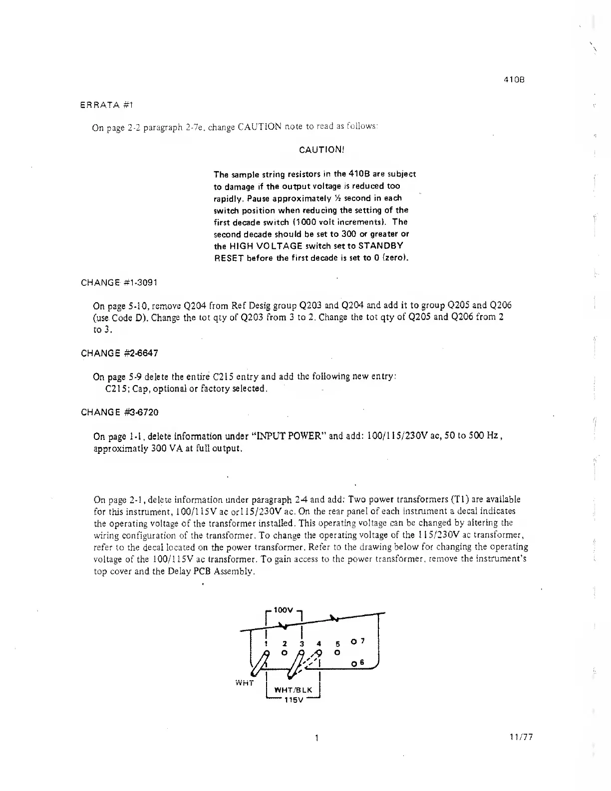
On page
2-1
,
delete information under paragraph
24
and
add: Two power transformers (Tl)
are available
for
this instrument,
100/1
15V
ac orl
15/230V ac. On
the rear panel of each
instrument a decal indicates
the operating voltage
of
the transformer
installed. This operating
voltage can be changed by altering
the
wiring configuration of
the transformer.
To
change the
operating voltage of the 1 1
5/230V ac transformer,
refer to the decal
located
on the
power transformer. Refer to
the drawing below for
changing the operating
voltage
of
the
100/1
15V
ac
transformer.
To
gain access to the
power transformer,
remove the instrument’s
top
cover
and the Delay PCB Assembly.
1
11/77