410B
On page 5-3, add
after
T!
description:
0
15/230V).
Add
another listing for
T1
as follows: T1
;
Transformer,
Aux.
(100/1
15V
);
Stock No.
-5600-3509
1
8;
Mir. -S9536;
Mfr.
Part
No.
-5600-3509
1
8;
Tot. Qty.
-1,
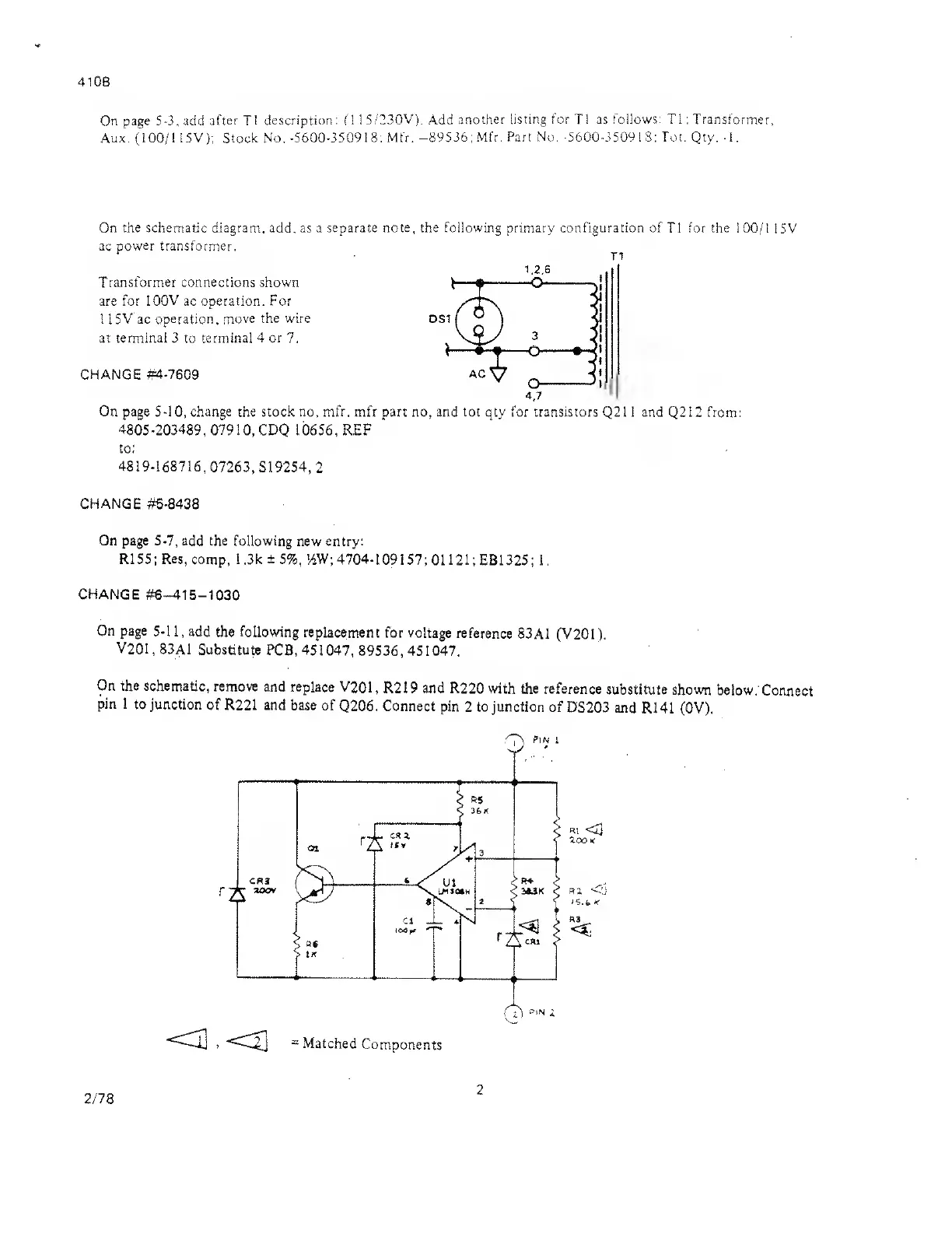
On the schematic diagram, add. as a separate note, the following primary configuration of
T1
for the
100/1
15V
ac power transformer.
Transformer connections shown
are for
100V
ac operation. For
1
1
5V ac
operation, move
the
wire
DSi
at terminal 3 to terminal
4 or 7.
CHANGE #4-7609
AC
On page 5-10, change the stock no, mfr. mfr part no, and tot qty for transistors
Q21 1 and
Q212
from:
4805-203489,
07910,
CDQ 10656, REF
to:
4819-168716,
07263,
S19254,
2
CHANGE #5-8438
On page 5-7, add the following
new entry:
R155;
Res,
comp, 1 ,3k
±
5%,
'AW;
4704-109157;
0112
1 ;
EB1325; 1
.
CHANGE
#6—415—1030
On page
5-11, add
the
following
replacement
for voltage
reference
83A1 (V201).
V201
,
83A1
Substitute
PCB,
451047,
89536,451047.
On the schematic,
remove
and replace V201,
R219 and R220
with the reference
substitute shown
below.
Connect
pin 1
to junction
of R221 and
base of
Q206. Connect
pin
2
to junction
of
DS203 and
R141 (0V).
«i
<3
zoo
<
RZ
<d
K
R3
=
Matched
Components
2/78
2