Performance Verification
4.8 Voltage Inputs 4
4-13
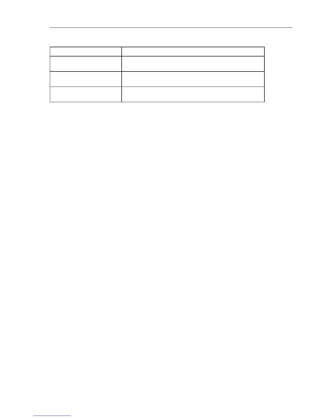
Table 4-8. Accuracy Check of Voltage Channel N (Neutral)
Set Calibrator to Readout at Voltage Channel N
115 V, 50 Hz, OPR Fluke 434-II: 113.8 ... 116.2 V
Fluke 435-II /437-II: 114.77 ... 115.23 V
230 V, 50 Hz, OPR Fluke 434-II: 228.8 ... 231.2 V
Fluke 435-II /437-II: 229.77 ... 230.23 V
460 V, 50 Hz, OPR Fluke 434-II: 458.8 ... 461.2 V
Fluke 435-II /437-II: 459.77 ... 460.23 V
15. Set the Calibrator to STBY.
Optional Test. Bandwidth Check of Channel N (*):
16. Set the Calibrator to 215 V, 50 Hz and OPR.
17. Now check the voltage channel N. Use the Calibrator’s field edit function
(AMPL/FREQ key) to adjust the Calibrator to an Analyzer readout of 215.0 V /
215.00 V.
18. Increase the frequency to 3 kHz.
Fluke 434-II: check for a readout of 204.2 V or more.
Fluke 435-II/437-II: check for a readout of 204.25 V or more.
19. Set the Calibrator to STBY.
4.8.4 Verification of voltage inputs in 400 V range
Accuracy Check of Channel A/L1, B/L2, C/L3:
1. Set the Analyzer to 400 V, 50 Hz nominal (SETUP menu, arrow and ENTER keys).
Press MENU, select Volts/Amps/Hertz, press F5 - OK.
2. To check the A/L1, B/L2, C/L3 inputs: connect the N input to Ground (See Figure 4-
3).
3. Set the Calibrator to 50 Hz, 200 V and then to OPR.
4. Fluke 434-II: check for a voltage readout V rms between 198.0 ... 202.0 V.
Fluke 435-II/437-II: check for a voltage readout V rms between 199.60 ... 200.40 V.
5. Check the 400 V range according to the table below.