Fluke 434-II/435-II/437-II
Service Manual
5-10
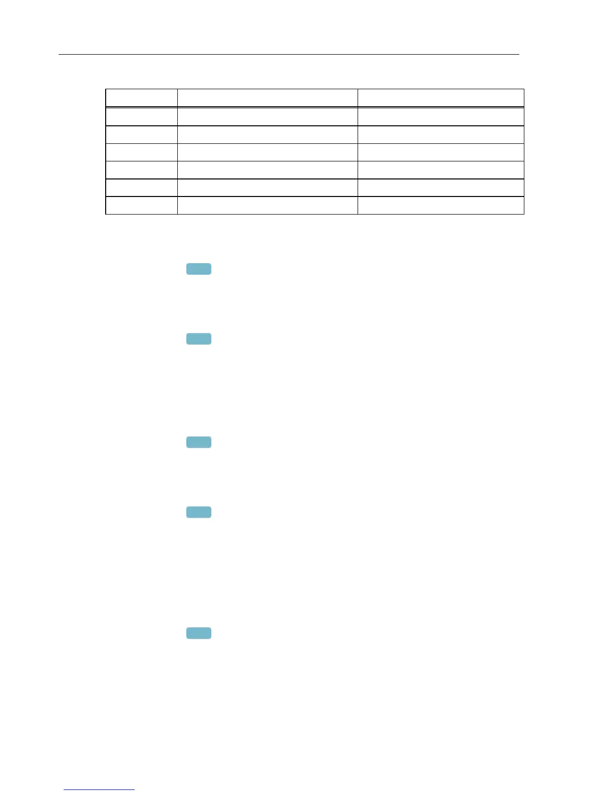
Table 5-1. Offset Adjustment of all Inputs
Cal step Description Calibrator Setting
CL 0300 OffsetLowVolt 0 V, 0 Hz, OPR
CL 0310 Offset125Volt 0 V, 0 Hz, OPR
CL 0320 Offset250Volt 0 V, 0 Hz, OPR
CL 0330 Offset500Volt 0 V, 0 Hz, OPR
CL 0340 Offset6KVolt 0 V, 0 Hz, OPR
--- --- STBY
5.6.3 Low voltage and current gain adjustment
Proceed as follows to do the Low Voltage and Current Gain Adjustment:
1. Press
F2
to select calibration step CL 0400.
2. Keep the Analyzer connected to the Calibrator as shown in Figure 5-3.
3. Set the Calibrator to source 0.67 V, 50 Hz .
4. Set the Calibrator to operate (OPR).
5. Press
F3
to start the calibration.
6. Wait until the display shows calibration status
:READY .
7. Set the Calibrator to Standby (STBY).
5.6.4 Current gain 10x
Proceed as follows to do the Current 10x Gain Adjustment:
3. Press
F2
to select calibration step CL 0405.
4. Connect the Analyzer to the Calibrator as shown in Figure 5-3.
8. Set the Calibrator to source 0.2 V, 50 Hz .
9. Set the Calibrator to operate (OPR).
10. Press
F3
to start the calibration.
11. Wait until the display shows calibration status
:READY .
12. Set the Calibrator to Standby (STBY).
13. Continue at section 5.6.5.
5.6.5 Voltage gain adjustment
Proceed as follows to do the Voltage gain Adjustment.
1. Press
F2
to select the first calibration step in Table 5-2 (CL 0410).
2. Connect the Analyzer to the Calibrator as shown in Figure 5-4: disconnect the current
inputs!