


Q
qestradaJul 26, 2025
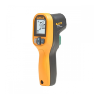
What to do if the Fluke Thermometer battery is dead?
- KKayla WrightJul 26, 2025
If the battery on your Fluke Thermometer is dead, replace it with a new one.
What to do if the Fluke Thermometer battery is dead?
If the battery on your Fluke Thermometer is dead, replace it with a new one.
Why won't the laser on my Fluke Thermometer work?
If the laser on your Fluke Thermometer isn't working, it could be due to low or dead batteries, or the ambient temperature being above 45°C (113°F). Try replacing the batteries first. If that doesn't solve the issue, ensure you are operating the unit in an environment where the ambient temperature is 45°C (113°F) or below.
Identifies hazards to avoid electrical shock or personal injury.
Protects thermometer and equipment from damage, EMF, static, thermal shock.
Provides telephone numbers and website for contacting Fluke support and registration.
Explains the laser sight function, its symbol, and automatic turn-off.
Details the function keys (A-G) and their labels on the thermometer.
Explains the various displayed functions (1-6) on the thermometer screen.
Guides on how to take a temperature measurement using the trigger and display.
Instructions on how to adjust emissivity using DIP switches and keys.
Explains how minimum and maximum values are displayed in the status bar.
Details setting the high alarm feature with visual and audible alerts.
Describes how to change unit settings using DIP switches (Lock, °C/°F, Buzzer, etc.).
Details calibration traceability to NIST and DKD.
Lists default settings for Emissivity/Gain and Hi Alarm.
| temperature range | -30 to 900°C (-25 to 1600°F) |
|---|---|
| ambient operating range | 0 to 50°C (32 to 122°F) |
| storage temperature | -20 to 50°C (-4 to 122°F) |
| display resolution | 0.1°C (0.2°F) |
|---|---|
| accuracy at 25°C | ± 0.75% of reading or ± 1K (± 1.5°F) |
| repeatability | ±0.5% of reading or ±1°C (±2°F) |
| power | 2 x 1.5 V Alkaline Type AA |
|---|---|
| battery life | 13 hrs. (50% laser and 50% backlight used) |
| response time (95%) | 250 mSec |
| dimensions | 200 x 170 x 50 mm (7.9 x 6.7 x 2 inches) |
|---|---|
| tripod mount | 1/4”-20 UNC |
| optical resolution (standard focus) | 60 : 1 (19mm spot size at 1.15M) |