6 Fluke Corporation Troubleshooting and Maintenance Using Fluke Loop Calibrators
2. Set the source current of the
707 to 20.000 mA using the
0-100% button. Note the
“output” meter display read-
ing. Adjust the span control
of the signal conditioner
one-half the delta from
20.000 mA.
Example: If the output dis-
play reads 21 mA. Adjust the
span control to 20.5 mA
(one-half the delta to the
required value of 20 mA).
3. Repeat this “one-half step”
process until the required
output is obtained. There are
signal conditioners that have
non-interactive controls that
do not require this procedure.
Verifying process scaled,
indicators
Scaled process indicators are
used to provide information
about a process either locally
or to a control room located a
distance away. These indicators
typically take a mA measure-
ment in series with the 4-20
mA loop signal or measure a
1 V-5 V drop across a 250 ohm
resistor in series with the 4-20
mA signal (a 4-20 mA signal
through a 250 ohm resistor
produces a 1 V to 5 V drop).
For indicators with a mA
input, the direct mA current
output of a 705, 707, 715 or
787 can be applied directly to
the input of the indicator. For
voltage input indicators, a 715
is ideal with its direct voltage
output. Or use a resistor across
the output of a 705, 707, or
787 as described previously
(“Using Fluke loop calibrators
as a voltage source”).
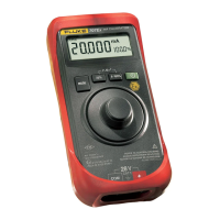
This example will show how
to use the 707 to verify a mA
input indicator. Make connec-
tions as shown in Figure 7.
1. Power the 707 up; the default
output should be 4 mA. Note
the indication, (digital or ana-
log) which should be
approximately 0%.
2. Depress the 0-100% button
on the 707; it is now in the
span check mode and is out-
putting 20 mA. Note the
indication (approximately
100%).
3. If testing the linearity is nec-
essary, use the 25% button to
step the mA output in 4 mA
steps and record the indica-
tions.
4. To calculate the errors in per-
cent, use the formula:
Nominal - Actual/Span x 100
Nominal is the ideal value,
actual is the recorded meas-
urement and span is 16 (4-20
mA = a 16 mA span).
Example: If the indication
with 0% applied is 1%, cal-
culate error as such: 0-1/16 =
.0625 X 100 = 6.25% error.
Calculate error based on the
recorded indications and
compare to the tolerances for
the indicator. If any of the
calculated errors are too
large, adjustment may be
necessary. Normally, there
are at least two adjustments
for analog indicators: zero
and span. The zero adjust-
ment is typically on
the
faceplate of the indicator.
5. With an output of 4.000 mA
from the 707 adjust the zero
indication. Span adjustment
is either a hard adjustment or
accomplished by bending a
linkage on the meter move-
ment. Refer to the manu-
facturer’s procedure for this
adjustment.
6.
Apply a 20.000 mA signal to
the indicator and make the
adjustment as specified. Once
the adjustment is completed,
re-verify the indicator and
confirm the adjustments had
the desired effect. If the indi-
cator still fails the test, it will
either need to be readjusted
until a satisfactory result is
attained, or replaced.
Voltage input indicators
The procedure for using the 707
to verify voltage input indicators
is almost identical to the proce-
dure outlined. The primary
difference is the addition of the
precision 250 ohm adapter.

 Loading...