Fluke Display Input Output
Reading % Input Voltage Current
4.000 0 1.000 V 4.000 mA
8.000 25 2.000 V 8.000 mA
12.000 50 3.000 V 12.000 mA
16.000 75 4.000 V 16.000 mA
20.000 100 5.000 V 20.000 mA
Calibrating the signal
conditioner
The following is a procedure
for calibrating a 1-5 V input, 4-
20 mA output signal
conditioner using the precision
current shunt constructed in
Figure 5.
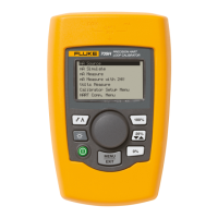
Step 1: Setting the Fluke 707
to source 4-20 mA
1. With the shunt assembly in
the “source” jacks, power
the 707 on.
2. Check the display. If the dis-
play does not read 4 mA,
turn the 707 off and on
again while holding the
mode button for two sec-
onds. The display should
now read 4.000 mA.
Step 2: Calibrating
1. Place a precision multimeter,
such as the Fluke 87 DMM,
set to dc current mode, in
series with the output of the
signal conditioner as shown
in Figure 6.
2. Connect the test leads from
the precision shunt assembly
to the signal conditioner
input terminals, observing
proper polarity.
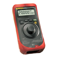
3. With the 707 set in the mA
source mode, the display
should read 4.000 mA (1.00
V across the shunt).
4. Adjust the zero control on
the signal conditioner for an
indication of 4.000 mA on
the DMM.
5. Press the 0-100% button on
the 707 until the display
reads 20.000 mA. Then
adjust the span adjustment
on the signal conditioner
until the display on the
DMM reads 20.000 mA.
6. Push the 0-100% button and
the 707 should read 4.000.
Verify the meter connected
to the output signal condi-
tioner reads 4.000 mA.
1
7. Calibration is now complete.
Note: Many manufacturers specify
a warm-up time prior to beginning
calibration.
Step 3: Checking linearity
Once zero and span controls
have been properly set, signal
conditioner linearity may be
verified using the following
procedure. This procedure will
check zero, 25%, 50%, 75%
and span settings for signal
conditioner linearity.
1. With the precision resistor
assembly in place, adjust the
source current of the Fluke
loop calibrator to 4 mA (1.0
V) using the 25% button.
The DMM displays 4 mA.
2. Using the 25% button, step
the source current to 25%,
50%, 75% and 100% and
note the corresponding val-
ues. Table 2 shows the
correct values of output for a
linear signal conditioner. (If
values differ from that
shown in Table 2 by more
than the linearity specifica-
tion of the signal
conditioner, contact the sig-
nal conditioner manufacturer
or replace the device.)
Making fine adjustments
Many signal conditioners with
0-20 mA and 4-20 mA outputs
are notorious for zero and span
control interaction. If, when
checking linearity in the cali-
bration section, your output
meter displayed a value higher
or lower than 4 mA, perform
the following steps to affect the
required 4 and 20 mA display
on the output meter.
1. Note the value above or
below 4 mA that was dis-
played on the output meter
when you returned to a
source value of 4.000 mA on
the 707. Adjust the zero con-
trol on the signal conditioner
so the value of the output
meter shows one-half the
difference of the remaining
mA value to 4 mA.
Example: If your display
reading at zero input in step
7 was 3.50 mA adjust the
output (with 4.000 mA
source current) to display a
reading of 3.75 mA, which is
one-half the delta toward
the desired value of 4 mA
(eg. 4.00 - 3.50 = 0.50;
0.05 / 2 + 3.50 = 3.75, or
one-half the difference
between the reading and
the desired value).
Troubleshooting and Maintenance Using Fluke Loop Calibrators Fluke Corporation 5
Figure 6
1
If your output meter displayed a value higher
or lower than 4 mA, consult the “Making fine
adjustments” section on this page.
Table 2. Correct value of output for a linear signal conditioner

 Loading...