725
Product Overview
4
V mA
LOO P
V mA
TC RTD
˚
C
˚
F
Hz
100%
25%
25%
RECALL
ZERO
MEAS
SOURCE
STORE
SETUP
0%
MULTIFUNCTION CALIBRATOR
725
8
7
6
5
4
3
2
1
sh05f.eps
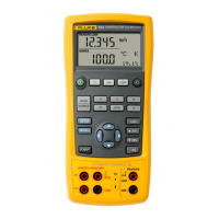
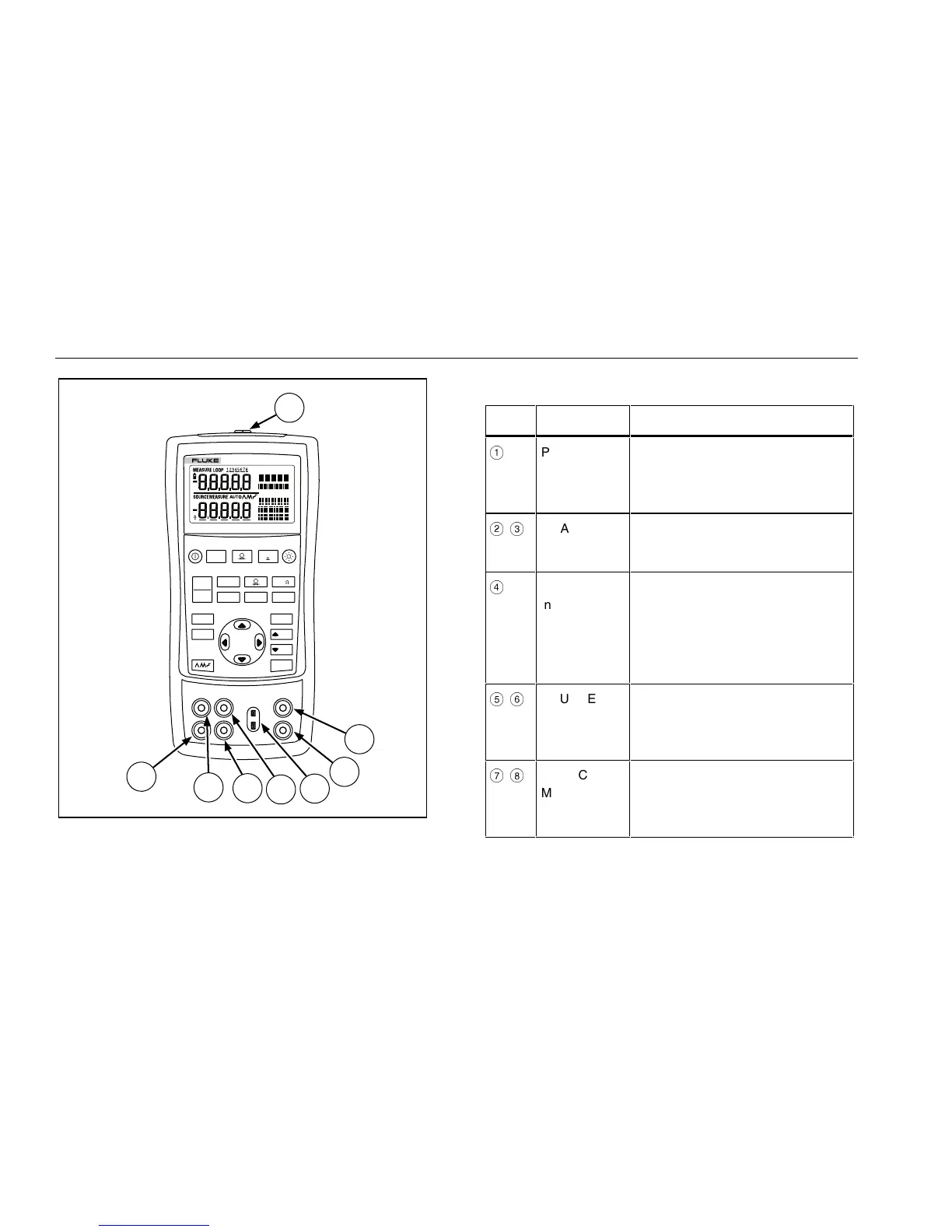
Figure 1. Input/Output Terminals and Connectors
Table 2. Input/Output Terminals and Connectors
No Name Description
A
Pressure
module
connector
Connects the calibrator to a
pressure module or the calibrator to
a PC for a remote control
connection.
B
,
C
MEASURE V,
mA terminals
Input terminals for measuring
voltage, current, and supplying loop
power.
D
TC
input/output
Terminal for measuring or
simulating thermocouples. This
terminal accepts a miniature
polarized thermocouple plug with
flat, in-line blades spaced 7.9 mm
(0.312 in) center to center.
E
,
F
SOURCE/
MEASURE V,
RTD, Hz, Ω
terminals
Terminals for sourcing or measuring
voltage, resistance, frequency, and
RTDs.
G
,
H
SOURCE/
MEASURE
mA terminals,
3W, 4W
Terminals for sourcing and
measuring current, and performing
3W and 4W RTD measurements.
 Loading...