procedure starting with turn
-
on. No equipment other
than the test leads will be required.
If
a problem
is
encountered, please recheck the battery, fuse, switch
settings, and test lead connections before contacting
your nearest authorized John Fluke Service Center.
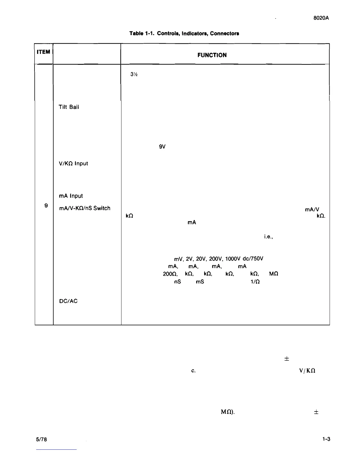
ITEM
NO.
NAME
FLlNCTlON
1 Display
A
3%
digit display (1999 max) with decimal point and minus polarity indication.
Used to indicate measured input values, overrange condition and low battery
condition.
NOTE
2
3
4
5
6
7
8
10
11
This procedure is intended to verify overall
instrument operation, and is not meant as a
substitute for the formal Performance Test
given in Section
4.
Limits shown exceed the
specifications because the procedure uses one
measurement function to check another.
a. Set the power switch to OFF and all range and
function switches to the released (out) position.
Power Switch
TiltBail
Battery Eliminator
Connector
Battery Compartment
and Cover
V/KQ lnput Connector
COMMON Input
Connector
mA lnput Connector
mA/V-KQ/nS
Switch
Range Switches
DC/AC Switch
b. Set the power switch to ON and observe the
display. It should read 00.0
f
0.1.
A slide switch used to turn the instrument off and on.
A removable fold
-
out stand which allows the instrument to be either tilted for
bench
-
top applications or hung from a hook in the absence of a work surface.
An external input power connector for use with the Model A81 Battery Eliminator
accessory. (A81 is available in a variety of voltage and plug configurations. See
Section 6).
Cover for the
9V battery and the current
-
protection fuse. The cover is removed by
pushing it away from the case screw.
Banana jack connector used as the high input for all voltage, resistance and
conductance measurements.
Banana jack connector used as the low or common input for all measurements.
Banana jack connector used as the high input for all current measurements.
A push
-
push switch (push on
-
push off, do not pull to select function) which
operates in conjunction with the high input connectors to select eitherthe
mA/V or
kQ (conductance) measurement functions. When in or depressed it selects kQ.
The out position selects mA or V depending upon the location of the high input
lead.
Interlocked push
-
button switches for selecting ranges, i.e., pressing the desired
range switch selects that 'range and cancels previous switch depressions. Do not
pull switches to select a range.
Voltage:
200
mV, 2V, 20V, 200V, lOOOV dc/750V ac
Current: 2
mA, 20 mA, 200 mA, 2000 mA
Resistance: 200Q, 2 kQ, 20 kQ, 200 kQ, 2000 kQ, 20 MQ
Conductance: 200 nS or 2 mS (S
=
siemens
=
1/Q
=
international unit of
conductance). Requires simultaneous depression of two range
switches.
A push
-
push switch (push on
-
push off, do not pull to select function) used to
select the ac or dc measurement function when measuring current or voltage.
When in, or depressed, theac function is selected. Out selects dc. Switch may be in
either position when making resistance or conductance measurements.
c.
Connect the red test lead to the V/Kn input
terminal.
d.
Touch the red probe tip to the COMMON
input terminal, and sequentially depress each of
the six grey range switches starting at the top
(20
Ma). The display should read zero
f
one
digit and the decimal point should be
positioned as follows: