Section
3
Theory
of
Operation
3
-
1. INTRODUCTION
3
-
2. This section of the manual contains an overall
functional description followed by a block diagram
analysis of the
8020A. A detailed schematic of the
8020A appears in Section
7.
3
-
3.
OVERALL FUNCTIONAL
DESCRIPTION
3
-
4.
The Model
8020A, as shown in Figure 3
-
1, is a
hand
-
held six function digital multimeter. It features a
total of 26 measurement ranges (V dc, 5; V ac,
5;
ohms,
6; conductance, 2;
mA dc,
4;
and mA ac, 4), a high
contrast easy
-
to
-
read, 3-112 digit, liquid crystal display;
long battery life (up to 200 hours); overload protection
for all ranges; and a minimum of components.
3
-
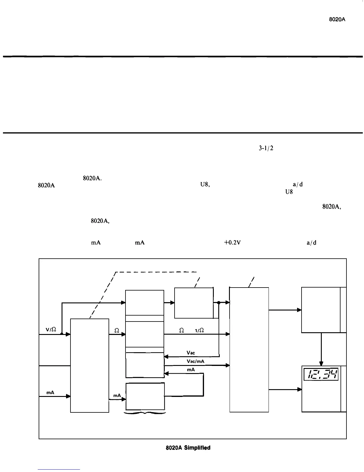
5.
Operation centers around a custom LSI chip,
U8, which comprises a dual slope ald converter and a
display driver. Peripherals to
U8 include range and
function switches, input signal conditioners, and the
display., When an input signal is applied to the
8020A, it
is routed through the range switches to one
-
of
-
four
input signal conditioners as determined by the function
switch setting. Each conditioner scales and, if necessary,
rectifies the input so that an acceptable dc input level
(
-
0.2 to +0.2V dc) is presented to the a/d converter.
Flgure
3
-
1.
8020A
Slmpllfled Block Diagram
3
-
1
r-----------
7
--
-
-
-
-
7
/ /
/
/
/
/
SIGNAL
CONDITIONERS
DC
ANALOG
DATA
b
AID
CONVERTER
AND
DISPLAY
DRIVER
Vdc
RANGE
SWITCHES
/
,/
V
/
/
I
VOLTAGE
DIVIDER
v
vln
DECIMAL
POINT
OHMS
CONVERTER
P
-1
DISPLAY
COMM
rnA
b
-
S1
a
OR
lln
Vac
RANGE
SWITCHES
AC
VaclrnA ac
CONVERTER
b
rnA
-
3
CURRENT
SHUNTS
b
FUNCTION
SWITCHES