2
-
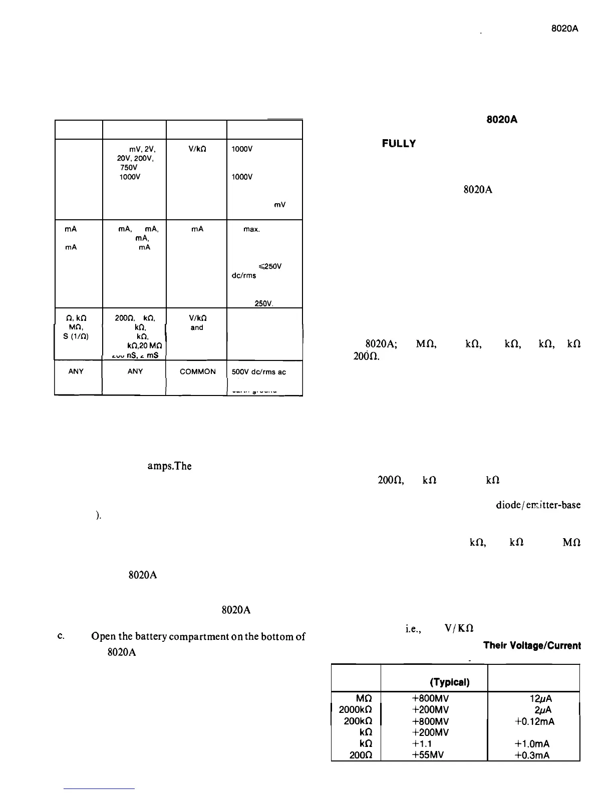
18.
Each measurement function and its associated
g.
Make sure the battery and its leads are fully
ranges are equipped with input overload protection. The within the confines of the battery compartment
overload limits for each function and range are given in
before closing the cover.
Table 2
-
1.
WARNING
DO NOT OPERATE THE
8020A UNTIL
THE BATTERY COVER IS IN PLACE
AND
FLILLY CLOSED.
SELECTED
FUNCTION
V dc
or
V ac
mA dc
or
mA ac
n,
kn
2
-
22.
AC
Measurement
2
-
23.
The ac ranges of the
8020A employ an average
responding ac converter. This means that the unit
measures the average value of the input, and displays it as
an equivalent rms value for a sine wave. As a result,
200 kn, COMMON
2000
kQ20 Mn
200 nS, 2 mS
with respect to
earth ground
SELECTED
RANGE
200 mV. ZV,
20V. 200V,
750V ac,
1000V dc
2
mA, 20 mA,
200 mA,
2000 mA
200Q 2 kn.
20 kn,
measurement errors are introduced when the input wave
form is distorted (non sinusoidal). The amount of error
depends upon the amount of distortion. Figure 2
-
2 shows
the relationship between sine, square and triangular
waveforms, and the required conversion factors.
2
-
24. Reslstance
INPUT
CONNECTIONS
V/kn
and
COMMON
mA
and
COMMON
V/kn
2
-
19. Fuse Replacement
MAX INPUT
OVERLOAD
1000V dc or
peak ac on dc
ranges.
1000V dc or
750V rms on ac
ranges
-
1 5 seconds
max on 200
mV
ac range.
2A
mar. Fuse
protected in
circuits with
open circuit
voltage
G250V
dc/rms ac.
Do not use
above
250V.
300V dc or rms.
2
-
20. The ac and dc current functions are fuse
protected (on all ranges) from inadvertent application of
current in excess of 2
amps.The fuse is locatedon the back
of the battery clip and is accessed by removing the battery
compartment cover. For replacement, use type AGX 2
(instruments that accommodate metric fuses use type
17 1 100
-
2
).
2
-
21.
Use the following procedure to install or replace
the fuse.
a.
Set the
8020A power switch to OFF.
2
-
25.
Six direct reading resistance scales are provided
on the
8020A; 20 MR, 2000 kR, 200 kR, 20 kR, 2 kR
and 200R. All scales employ a two wire measurement
technique. As a result, test lead resistance may influence
measurement accuracy on the 200R range. To determine
the error, short the test leads together and read the lead
resistance. Correct the measurement by subtracting the
lead resistance from the unknown reading. The error is
generally on the order of 0.2 to 0.3 ohms for a standard
pair of test leads.
2
-
26. In
-
circuit resistance measurements can be made
using the
200R, 20 kfl and 2000 kR ranges. The open
circuit measurement voltage produced on these ranges is
not sufficient to forward bias silicon
diode/er?;.itter-base
junctions, and thus, enables resistance values to be
measured without removing diodes and transistors from
the circuit. Conversely, the 2
kR, 200 kR and 20 MR
ranges produce a measurement voltage sufficient to
forward bias a P
-
N junction. These ranges enable both
diode
-
and transistor
-
junction checks to be made
b.
conveniently. Maximum open circuit voltage and short
Remove test leads from external circuit
circuit current for each resistance range is given in Table
connections and from the
8020A input ter
-
minals.
2
-
2. All values shown are referenced to the COMMON
input terminal;
i.e., the V/KR terminal is positive.
c.
Open
the
battery 'Ompartment
On
the
bottom
of
Table
2
-
2.
Redstance Range and Thelr Voltage/Current
the 8020A using the method shown in Figure 2
-
1.
Capablllty
e.
Carefully remove and replace the defective fuse.
2000kn +200MV
+O.
1 &A
I
200kn
I
+8OOMV
I
+0.12mA
I
d.
Extend the battery and fuse by sliding toward
connector end. and then tilting out of
compartment.
Range
20 Mn
f.
Return the battery and fuse to the battery
compartment. Insert leads first, then connector.
Tilt battery down into the compartment.
Full Scale
Voltage
(Typical)
+800MV
20 kn
2 kn
200n
Short Clrcult
Current (Typical)
+O.
1&A
+200MV
+1.1 V
+55MV
+O. 12mA
+l
.OmA
+0.3mA