Theory of Operation
DETAILED DESCRIPTION
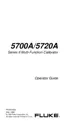
Figure
2-2.
Ohms
Function
ROTARY
SWITCH 2-1
0.
Rotary
switch
SI
FRONT
selects and routes the input signals.
Function codes
for switch
SI REAR
are
shown
in Table
2-1.
Range switch
S2 signals the
microcomputer
U2
for
the
manual ranging
and automatic Touch Hold® function.
CR1 acts
as protection for
U1
if the
battery
is
installed backwards.
C2 is
part
of the
power-on
reset for microcomputer
U2.
A/D
CONVERSION
2-1
1
.
Analog-to-digital
(a/d)
conversion
is accomplished within
U1
using
a
modified
dual-
slope
a/d converter circuit
(See Figure 2-3, AC and
A/D Converter.)
Since the
a/d conversion process is essentially
a
dual
slope method,
two voltages are
required
to complete
a
measurement cycle.
One is the unknown input
and the other is
the reference
voltage.
Conditioned
input
signals are routed to the
a/d
converter
in
Ul, where
they
are
integrated.
The reference
voltage developed
by
reference
supply VR1,
R15, R16, and R8
is routed
to
the
a/d converter in Ul, where
it is
used for the
integrate reference
(de-integrate) portions
of the measurement
cycle.
C7 stores offsets of
the
buffer, integrator,
and comparator
amplifiers
of the a/d
converter.
The gain of
the
buffer is determined
by
the resistors
of Z1
between pins
8, 9,
and
10.
C8
is the integrator capacitor.
®
Touch Hold is
a
registered
trademark
of the John
Fluke Mfg.
Co., Inc.
2-5

 Loading...