Maintenance
PERFORMANCE TESTS
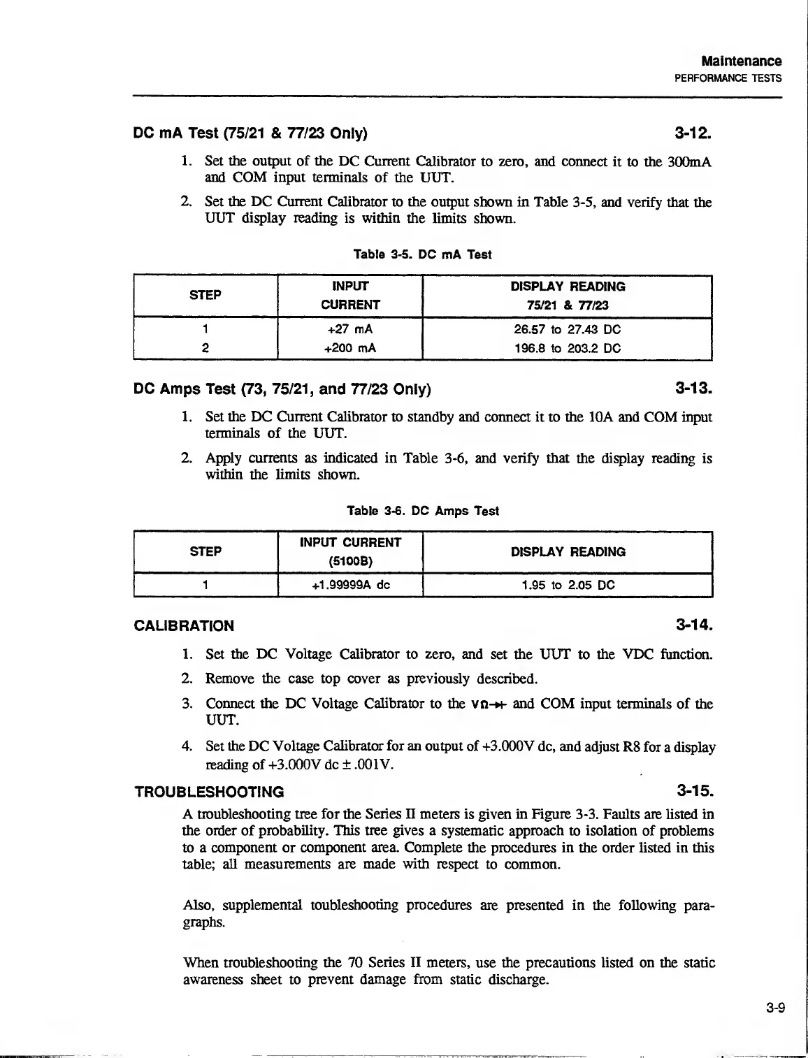
DC
mA Test
(75/21 &
77/23
Only)
3-12.
1.
Set
the
output of the DC Current
Calibrator
to
zero, and
connect it
to the 300mA
and COM input terminals
of the UUT.
2.
Set
the DC Current
Calibrator to the
output shown in Table
3-5, and verify that
the
UUT display reading
is within
the limits shown.
Table
3-5.
DC mA Test
STEP
INPUT
DISPLAY
READING
CURRENT
75/21 &
77/23
1
+27 mA
26.57 to 27.43
DC
2 +200 mA
196.8 to
203.2 DC
DC
Amps Test
(73,
75/21,
and
77/23 Only)
3-13.
1.
Set
the DC Current
Calibrator to standby
and
connect it
to
the
10A and COM input
terminals of the
UUT.
2. Apply currents
as
indicated
in Table 3-6, and verily that the display
reading is
within the limits
shown.
Table
3-6.
DC Amps Test
STEP
INPUT CURRENT
(5100B)
DISPLAY READING
1 +1.99999A dc 1.95 to 2.05
DC
CALIBRATION
3-14.
1. Set
the DC Voltage
Calibrator to
zero,
and
set
the UUT to the VDC function.
2.
Remove
the case top cover as previously described.
3. Connect the DC Voltage Calibrator to the
vn-*+- and
COM input terminals
of the
UUT.
4.
Set the DC Voltage
Calibrator for an
output of +3.000V
dc, and
adjust R8
for a
display
reading of
+3.000V dc ± ,001V.
TROUBLESHOOTING
3-15.
A troubleshooting tree for the Series n meters is
given
in Figure
3-3.
Faults are
listed in
the
order
of
probability. This tree gives a
systematic
approach
to isolation of problems
to a component or
component area.
Complete the procedures in the order
listed
in
this
table;
all measurements are made
with
respect to common.
Also, supplemental toubleshooting procedures
are presented in the following
para-
graphs.
When troubleshooting the 70
Series II
meters,
use
the precautions listed on the static
awareness sheet
to
prevent
damage from
static discharge.
3-9

 Loading...