EasyManua.ls Logo

Fluke LS-1310 - User Manual

Fluke LS-1310
10 pages
Print Icon
To Next Page IconTo Next Page
Loading...
PN 688967
November 1997, Rev. 1, 9/01
1997, 2001 Fluke Networks, Inc. All rights reserved. Printed in USA. Product names are trademarks of their respective companies.
LS-1310/1550
Laser Source
Service Information Sheet
Introduction
This Service Information Sheet provides the
following service information for the LS-1310/1550
Laser Source (hereafter referred to as "the laser
source").
Precautions and safety information
Parts and service information
Specifications
Cleaning procedures
Required equipment
Performance tests
Calibration adjustments
Diagrams showing calibration measurement
and adjustment points
Parts and accessories lists
For operating instructions, refer to the
LS-1310/1550 Laser Source Instruction Sheet.
Precautions and Safety
Information
Always clean the fiber optic connectors before
use.
Before testing, let the laser source stabilize for
2 minutes after you turn it on.
Warning: Class I Laser Product
To avoid injury, do not service the
source unless you are qualified to do so.
To avoid possible exposure to
hazardous laser radiation and to prevent
eye damage
Never look directly into the source
connector. Though the laser radiation is
invisible, it can damage your eyes.
Do not modify the source.
Do not magnify or otherwise modify the
laser output. Use only approved
connectors and adapters.
Do not use controls, adjustments, or
procedures not documented or approved
by Fluke Corporation.
Caution
While servicing the laser source, always
follow guidelines for preventing
electrostatic discharge (ESD). Otherwise,
ESD can damage sensitive components,
causing immediate or delayed failure of
the source.
Parts and Service
The source is warranted to be free from defects in
material and workmanship for one year, while
under normal use. Parts and repairs are warranted
for 90 days. Refer to the laser source instruction
sheet for the complete warranty statement.
To order parts, or for warranty service, contact
Fluke as follows:
U.S.A.: 1-888-993-5853
Canada: 1-800-363-5853
Europe: +31-402-675-200
Japan: +81-3-3434-0181
Singapore: +65-738-5655
Anywhere in the world: +1-425-446-4519
For operating assistance in the USA, call
1-800-283-5853.
Visit the Fluke Networks web site at
www.flukenetworks.com.
Advanced Test Equipment Rentals
www.atecorp.com 800-404-ATEC (2832)
®
E
s
t
a
b
l
i
s
h
e
d
1
9
8
1
Question and Answer IconNeed help?

Do you have a question about the Fluke LS-1310 and is the answer not in the manual?

Summary

Introduction

Precautions and Safety Information

Parts and Service

Specifications

Required Equipment

Performance Tests

Calibration Adjustments for Serial Numbers < 79130000

Step 1: Preparing for Calibration

Outlines initial setup and preparation steps before performing calibration procedures.

Step 2: Checking the Laser Drive Voltage

Details how to check laser diode drive voltage and verify the low battery detection circuit.

Step 3: Calibrating and Adjusting the 1310 nm Circuit

Guides through calibration and adjustment of the 1310 nm laser diode and modulation circuits.

Step 4: Calibrating and Adjusting the 1550 nm Circuit

Guides through calibration and adjustment of the 1550 nm laser diode and modulation circuits.

Step 5: Reassembly and Final Test

Covers reassembly steps and final performance verification after calibration.

Calibration Adjustments for Serial Numbers ≥ 79130000

Step 1: Preparing for Calibration

Details initial setup and preparation steps for calibration of later serial numbers.

Step 2: Checking the Laser Drive Voltage

Explains how to check laser drive voltage and verify the low battery detection circuit for later serial numbers.

Step 3: Calibrating and Adjusting the 1310 nm Circuit

Guides calibration and adjustment of the 1310 nm circuit for later serial numbers.

Step 4: Calibrating and Adjusting the 1550 nm Circuit

Guides calibration and adjustment of the 1550 nm circuit for later serial numbers.

Step 5: Adjusting the 2 kHz Modulated Signal

Details how to adjust the 2 kHz modulated signal for later serial numbers.

Step 6: Reassembly and Final Test

Covers reassembly and final testing for later serial numbers.

Parts and Accessories

Overview

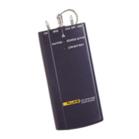
The Fluke LS-1310/1550 Laser Source is a Class 1 laser product designed for testing and calibrating fiber optic networks. It emits laser radiation at two wavelengths: 1310 nm and 1550 nm, making it suitable for singlemode fiber applications. The device is battery-powered and portable, intended for use by qualified personnel.

Function Description

The primary function of the LS-1310/1550 Laser Source is to provide a stable optical power output at specified wavelengths for testing and calibration of fiber optic systems. It can operate in two modes: Continuous Wave (CW) and Modulated (MOD). In MOD mode, it outputs a 2 kHz ±100 Hz signal with a 50% ±5% duty cycle, which is useful for identifying and tracing fibers. The device is designed to be used in conjunction with a fiber optic power meter to measure optical loss in fiber optic cables.

Important Technical Specifications

  • Emitter Type: Laser
  • Laser Classification: Class 1
  • Safety Compliance: Complies with ANSI/ISA S82.01-1994, CSA C22.2 No. 1010.1-92, EN61010.1: 1993.
  • Output Wavelengths:
    • 1310 nm ±20 nm
    • 1550 nm ±30 nm
  • Output Connector: Singlemode ST
  • Output Power (CW): -10 dBm (100 µW) adjustable
  • Output Level Stability (at 25 °C after 15-minute warm-up):
    • ±0.2 dB over 1 hour
    • ±0.4 dB over 8 hours
  • Temperature Range:
    • Operating: 0 °C to 40 °C
    • Storage: -10 °C to +60 °C
  • Power Source: 9 V battery
  • Dimensions: 17.4 cm x 7.6 cm x 3.8 cm (6.9 in x 3.0 in x 1.5 in)
  • Weight: 266 g (9.38 oz)
  • Battery Life: 16 hours typical (alkaline)
  • Indicators: SOURCE ACTIVE (power on) LED, LOW BATTERY LED

Usage Features

The laser source is designed for straightforward operation with a focus on safety and accuracy.

  • Wavelength Selection: A power switch allows selection between 1310 nm and 1550 nm output.
  • Operating Modes: A CW/MOD switch allows selection between Continuous Wave (CW) and Modulated (MOD) output.
  • Stabilization Time: The device requires a 2-minute stabilization period after being turned on to ensure accurate readings. For performance tests, a 5-minute stabilization is recommended.
  • Low Battery Indication: A LOW BATTERY LED flashes briefly upon startup and illuminates when the battery voltage is low, indicating the need for replacement.
  • Active Source Indication: A SOURCE ACTIVE LED illuminates when the laser source is powered on and operating.
  • Connector Type: The device uses an ST connector for fiber optic connections, requiring ST/ST singlemode fiber patch cables for testing.
  • Safety Precautions: Users are warned against looking directly into the source connector due to invisible laser radiation that can cause eye damage. Servicing should only be performed by qualified personnel. Modifications to the source, magnification of the laser output, or use of unapproved connectors/adapters are prohibited.

Maintenance Features

Regular maintenance, particularly cleaning and calibration, is crucial for the optimal performance and longevity of the LS-1310/1550 Laser Source.

  • Connector Cleaning: Contaminated connectors are a common cause of problems. Users are instructed to always clean fiber optic connectors before use. This involves gently wiping with an optical-grade tissue or swab dampened with optical-grade alcohol, and using filtered, compressed air to remove loose dirt and dust.
  • Dust Caps: The connector should always be covered with a dust cap when not in use to prevent contamination.
  • Annual Calibration: To maintain specifications, the laser source requires annual calibration. The manual provides detailed calibration adjustment procedures for different serial number ranges (pre-79130000 and post-79130000).
  • Performance Tests: A series of performance tests are outlined to verify proper operation. These tests involve using a calibrated fiber optic power meter to check output power, signal frequency, and duty cycle in both CW and MOD modes at both wavelengths. If the device fails these tests after cleaning and verifying connections, it indicates a need for calibration adjustments or repair.
  • Electrostatic Discharge (ESD) Prevention: While servicing, strict adherence to ESD prevention guidelines is emphasized to protect sensitive components from damage, which could lead to immediate or delayed failure.
  • Repair and Parts Ordering: The device is warranted for one year against defects in material and workmanship under normal use, with parts and repairs warranted for 90 days. Contact information for Fluke is provided for ordering parts or obtaining warranty service.
  • Potentiometer Adjustment: Calibration involves adjusting internal and external potentiometers (e.g., R4, R14, R24, R35 for earlier serial numbers; R12, R31, R39, R40 for later serial numbers) to fine-tune laser drive current and output power.
  • Modulated Signal Adjustment: For later serial numbers, adjustment of R29 is specified to ensure the correct frequency and duty cycle of the modulated signal.
  • Insulating Varnish: After calibration adjustments, applying insulating varnish (e.g., red GLPT) to adjusted potentiometers is recommended to secure their settings.
  • Battery Replacement: The device uses a standard 9 V battery, which is easily accessible by removing the battery door.
  • Disassembly/Reassembly: Detailed steps are provided for disassembling and reassembling the unit for calibration, including removal of the top case, external retaining nuts, and the circuit board, with careful instructions to avoid straining the fiber optic cable.

Fluke LS-1310 Specifications

General IconGeneral
BrandFluke
ModelLS-1310
CategoryMeasuring Instruments
LanguageEnglish

Related product manuals