General
Information
WARNING:
Before
turning
on
the
instrument,
ensure
that it has been
installed
In accord-
ance with the Installation
Instructions
outlined in
Chapter
1 of the
Operators Ma-
nual.
This performance procedure is intended to:
—
Check the
instrument’s
specification.
—
Be used for
incoming
inspection to determine the
accept-
ability of newly purchased
instruments
and
recently reca-
librated instruments.
—
Check the necessity of re calibration after the
specified
recalibration intervals.
NOTE: The procedure does not check
every
facet of the in-
strument’s calibration; rather, it is
concerned
primarily
with those parts of the instrument which
are essential
for determining the function of the instrument
it is
not necessary to remove the cover of the
instrument
to
perform
this procedure.
If
the test is started less than 20 minutes after
turning
on
the instrument, results may be out of
specification,
due to
insufficient warm-up time.
Required
Test
Equipment
Type
of
instrument
Required
Specifications
Suggested
Instrument
LF Synthesizer
Square;
Sine up to 2 MHz
PM5193
Digital Multimeter
to 300
Vac
&
Vdc
PM2518; Fluke 77
Power Splitter
PM9584/02
T-piece
PM9067; Y9107
Termination
son
PM9585; Y9103
Low pass
filter
50 kHz
PM9665B/01
Reference
oscillator
10MHz
1*i'10“^
for
01 to 04
oscillator
5MHz for
05 osc.
Philips counter
with calibrated
PM9691
PM
6685R
*)
HF signal
generator
to
2.1
GHz for
PM9621, 5 GHz
for PM9624 & 25
Fluke 6062A
Wiltron
6717B-20
*)
Pulse
Generator
to 125 MHz
PM5786B;PM5781
Oscilloscope
with
probes
350 MHz PM3295
Power Supply
min 40
Vdc
PM2811/113,
PE1537;
PE1542
BNC-cables
5 to
7
cables
Table
2-1
Recommended Test Equipment
*)
This test
equipment in needed if an option
Is installed.
Preparations
Power up your
instruments
at least 20 minu-
tes before checking to
let them reach normal
operating temperature.
Failure
to do so may
result in certain
test
steps not meeting
equip-
ment
specifications.
Front Panel
Controls
Power-On Test
At
power-on the timer/counter
performs an
automatic
self-
test of
the
following:
-
Microprocessor
-
RAM
-
ROM
-
Measuring
circuits
It also
displays
the GPIB address.
If there are any
test
failures, an error
message
is shown.
Internal
Self-Tests
The built-in test
programs from
the power-on
test
can also
be activated from
the front panel as
follows:
-
Enter the Auxiliary Menu
by pressing AUX
MENU.
-
Select the
test
submenu by pressing
SELECT up or
down.
-
Enter the test menu by
pressing
the ENTER
key.
Selections
for internal self-tests are:
1
TEST
RO
(ROM)
2
TEST RA (RAM)
3 TEST ASIC (Measuring
Logic)
4 TEST
DISP
(Display Test)
5 TEST ALL (Test 1
to
4 in
sequence)
s.B.B.aae.aaaQ-£
„
m+im
UMAX
S
XMIN
Hz
DI3PLR0LD MEAN
,
SINGLE
ST DEV
ENTER V
MB.(OFI¥' AUX
FREQ
A
FREQC PER A RATIO
A/B
RATIO
C/B
P
WIDTH
A TIMEA-B PHASE A-B
ARM
ARM
TOTA-BMAN
TOTAfUlB
TOTAR B DUTY FA RISBFALLA
VOLTA
MAX/MIN STA+ STOf
REMOTE
E>aREF RLTEH
lEOMfl 0=1=1
A±TB =1= 150MQ
COMA
CHECK HOLD
SRQ LO BAT 10X DCAC BURST AID'O
PRF
DCAC
1DX
OFF
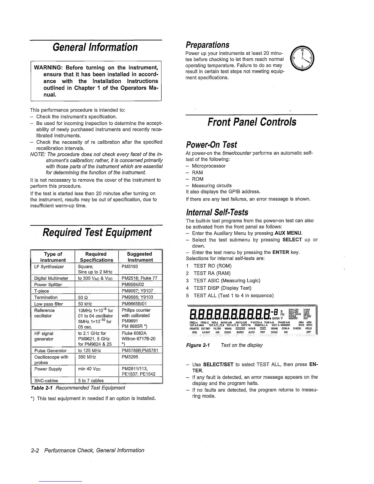
Figure
2-1
Text on the display
-
Use SELECT/SET to
select
TEST ALL,
then
press EN-
TER.
-
If any fault is
detected, an error
message
appears on the
display
and the program halts.
-
if no
faults are
detected, the program
returns to measu-
ring mode.
2-2
Performance
Cheeky
General
Information
 Loading...


