How
to
Read
the
Diagrams
This chapter
contains
circuit
diagrams and
component
layout in-
formation.
Each diagram contains a list of the ICs
used. These lists indica-
tes
the
connections that are not
shown in the diagram, such
as
GND
and supply voltages.
Signals
The signals in the counter are
named
after what they do, e.g.
LEAD-EDGE
is used
as control current to
the leading
edge cir-
cuits.
Two different
types of
arrows are used to mark
references for
continued connection somewhere else in
the diagram.
~t>
This arrow
is used if the
reference is
directed to a
point located on the same page.
~\y
/1
.A1
Thjs arrow is used if the
reference
is directed
to
a
point located on
another page.
The example
means that the
point is on sheet
1,
coordinate A1.
Colored Areas
The coloured
areas in the diagrams
represent following
functions:
=
Integrated circuits
I
I
=
Trim points,
test
points or jumpers
=
Connectors
Circuit
Symbols
The diagrams
are computer
drawn.
The symbols
conform
to
lEC
standards. These
symbols
are designed
to
be logical and
easy to read.
The
component
number is written
above the symbol.
Inside
the symbol at the top is an
abbreviated
description
of the
circuit’s
function.
Pin
numbers are
written outside
the symbol
and,
if the circuit is
complex, the
pin
functions are
written inside.
A small circle on
a pin indicates
that the input/output
inverts
the
signal.
The
component name
is written
below
the symbol.
The signal flow
through the circuit is
always from
left to right.
Resistors,
Capacitors,
Diodes,
Transistors and
Other
Components.
These
components are
similar to
the
old-fashioned,
hand-
drawn symbols.
They have their
component number
above and
their
value or component
name
below.
A resistor
contained
In
a resistor
network has a frame
drawn
around it and one of
the pin numbers
is
written to the
left
or
be-
low it.
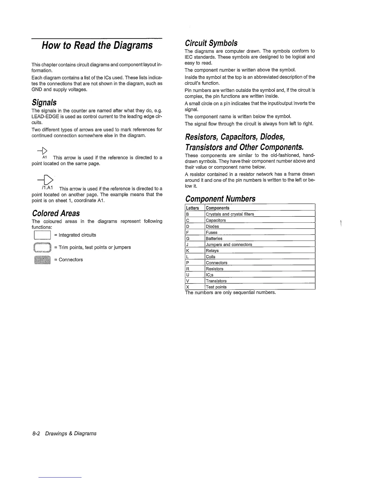
Component
Numbers
Letters
Components
B Crystals and
crystal
filters
C
Capacitors
D Diodes
F
Fuses
G
Batteries
J
Jumpers and
connectors
K
Relays
L
Coils
P
Connectors
R
Resistors
U IC;s
V
Transistors
X
Test points
The
numbers are only
sequential
numbers.
8-2
Drawings
&
Diagrams