EXT ARM
input
-
Select
non AUTO.
-
Settings for pulse generator: single
shot pulse,
amplitude
TTL
=
0-2
Vpp, and duration
=
10
ns.
-
Connect
a pulse generator to EXT
ARM input.
-
Press START ARM key.
-
Press
SELECT
key until display
shows ’POS’, confirm
with ENTER key three times.
-
The
counter
does not measure.
-
Apply
one single pulse
to
EXT
ARM input.
-
The counter measures once and
shows
10 MHz on the
display.
TRIG LEVEL A&B Outputs
-
Press the PRESET key, to set the
timer/counter in the
default
setting.
-
Connect a voltmeter to TRIG
LEVEL A(B)
OUT at the
rear.
-
Set the Trigger
Level (SET A/B)
on the
front
to the follo-
wing
values,
and verify the
voltmeter’s
readout:
SET A(B) Readout
Pass/Fail
Input A Input
B
+
5.00
V
+
5 V ± 0.28V
-
5.00
V
-
5
V
±
0.28V
0.00
V
0 V ± 0.03V
Table
2-8
Trigger level outputs
check
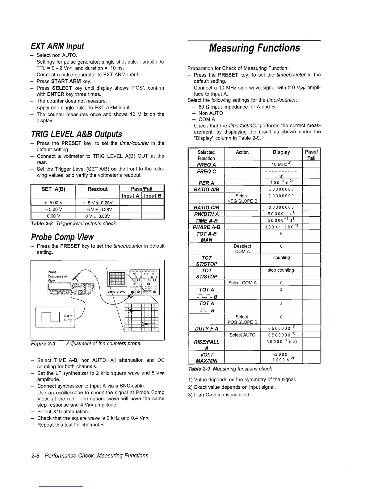
Probe
Comp
View
—
Press the
PRESET key to set the
timer/counter in default
setting.
Figure
2-3
Adjustment of the
counters
probe.
“
Select
TIME
A-B, non AUTO, XI
attenuation
and
DC
coupling for
both channels.
-
Set the
LF
synthesizer
to 2 kHz square
wave
and 8 Vpp
amplitude.
-
Connect
synthesizer to Input
A via a
BNC-cable.
-
Use an
oscilloscope
to check the signal
at Probe Comp
View, at the
rear.
The square wave will
have
the same
step response
and
4 Vpp amplitude.
-
Select XI 0
attenuation.
-
Check that
the square
wave
is
2 kHz and 0.4
Vpp.
-
Repeat this
test
for channel
B.
Measuring
Functions
Preparation for Check of
Measuring Function:
-
Press the
PRESET
key,
to set the
timer/counter in
the
default setting.
-
Connect a 10
MHz sine
wave signal
with
2.0 Vpp ampli-
tude to input A.
Select the following
settings for the
timer/counten
-
50 £1 input impedance for
A and B
-
Non
AUTO
-
COMA
-
Check
that the
timer/counter
performs
the
correct
meas-
urement, by displaying
the result as
shown
under the
"Display"
column in Table
2-9.
Selected
Function
Action
Display
Pass/
Fail
FREQ
A
10
MHz
FREQC
3)
PER
A
100‘®
s
RATIO A/B
10000000
Select
NEC
SLOPE
B
10000000
RATIO
C/B
00000000
PWIDTHA
50
000"®
s''^
TIME A-B
50 0
00"®
PHASE A-B
180
or
-180'’^
TOT A-B
MAN
0
Deselect
COMA
0
TOT
ST/STOP
counting
TOT
ST/STOP
stop
counting
Select COM A 0
TOT A
JX_TL
B
1
TOT A
^
B
1
Select
POS SLOPE B
0
DUTY FA
0500000
Select AUTO 0500000
RISE/FALL
A
3 0
000"®
S2)
VOLT
MAX/MIN
+100 0
-
1 0 0 0
V
Table
2-9
Measuring
functions
check
1)
Value
depends on the
symmetry
of
the signal.
2)
Exact value
depends on input signal.
3)
if an
C-option is installed.
2-6
Performance
Check,
Measuring
Functions
 Loading...


