Reference
Oscillators
X-tal
oscillators
are
affected
by a number of external condi-
tions
like
ambient temperature and supply voltage but also
by
ageing.
Therefore it is hard to give limits for the allowed
frequency deviation.
The
user
himself must decide the li-
mits depending
on his application, and recalibrate the oscii-
lator accordingiy. See the Preventive
Maintenance chapter.
Oscillator Max
temperature
dependence
Max
ageing
month
Max
ageing year
Standard.
01
±100 Hz ±5
Hz
±50
Hz
PM
9678B,
02
±10 Hz ±1
Hz
±5
Hz
PM
9690,
04
±0.15 Hz ±0.2
Hz
±1 Hz
PM
9691,
05
±0.05 Hz ±0.1
Hz
±0.75 Hz
Table
2-6
Deviation (for PM 9690 and PM 9691 after
48
hours
warm
up time)
To check the accuracy of the
oscillator
you
must have
a
ca-
librated reference signal that
is
at least
five
times as stable
as the oscillator that you
are testing,
see the following ta-
ble. If you use a
non
10 MHz reference, you can use the
mathematics in
PM
6681 to
multiply the reading.
-
Set the counter to default settings
by pressing
PRESET.
“
Connect the reference to input A
-
Check the readout against
the
accuracy requirements of
your application.
•
Acceptance Test
As
an acceptance test
the
following table gives a worst case
figure after 30 minutes warm
up
time.
All deviations that can
occur in a year are added together.
Oscillator Frequency
readout Suitable
reference
Pass
/Fail
Standard, 01 10.00000000 MHz
± 150
Hz
PM
9678B
PM 9678B, 02 10.00000000
MHz
±15
Hz
PM 9690
PM
9690,
04
10.00000000
MHz
±2Hz
PM 6685B
PM
9691,
05 10.00000000 MHz
±1Hz
PM 6685B
Table
2-7
Acceptance test for
oscillators
Resolution Test
-
Connect
a
pulse
generator
to a power splitter.
-
Connect one side
of the
power splitter to the A input of
the
counter
via a coaxial cable.
-
Connect the other side
of the power splitter to the B in-
put of the counter.
Settings for the pulse generator,
-
Amplitude
=
1 Vpp, (high
level
+1V and low
level
OV)
-
Period approximately
1
|lis
-
Duration
=
approximately 50
ns
-
Rise time
2
ns
Settings for the timer/counter, after Preset:
-
Function
=
Time A-B
-
Single
—
Press STAT key under PROCESS
—
Press SELECT key until display show ’ST DEV’.
—
Meas Time
=
50
ills
—
A and B inputs:
-
50 O input impedance
-
Non AUTO
-
Trigger level
=
0.5V
-
DC
coupling
The result should
be (std
dev)
<
0.05'®
s.
Rear Input/Output
10 MHz OUT
-
Connect an oscilloscope to the 10 MHz output on
the
rear of the counter. Use coaxial cable and 50
Q. termina-
tion.
-
The output voltage is sine wave shaped and
should be
above 500 mV rms
(1
.4 V
p-p).
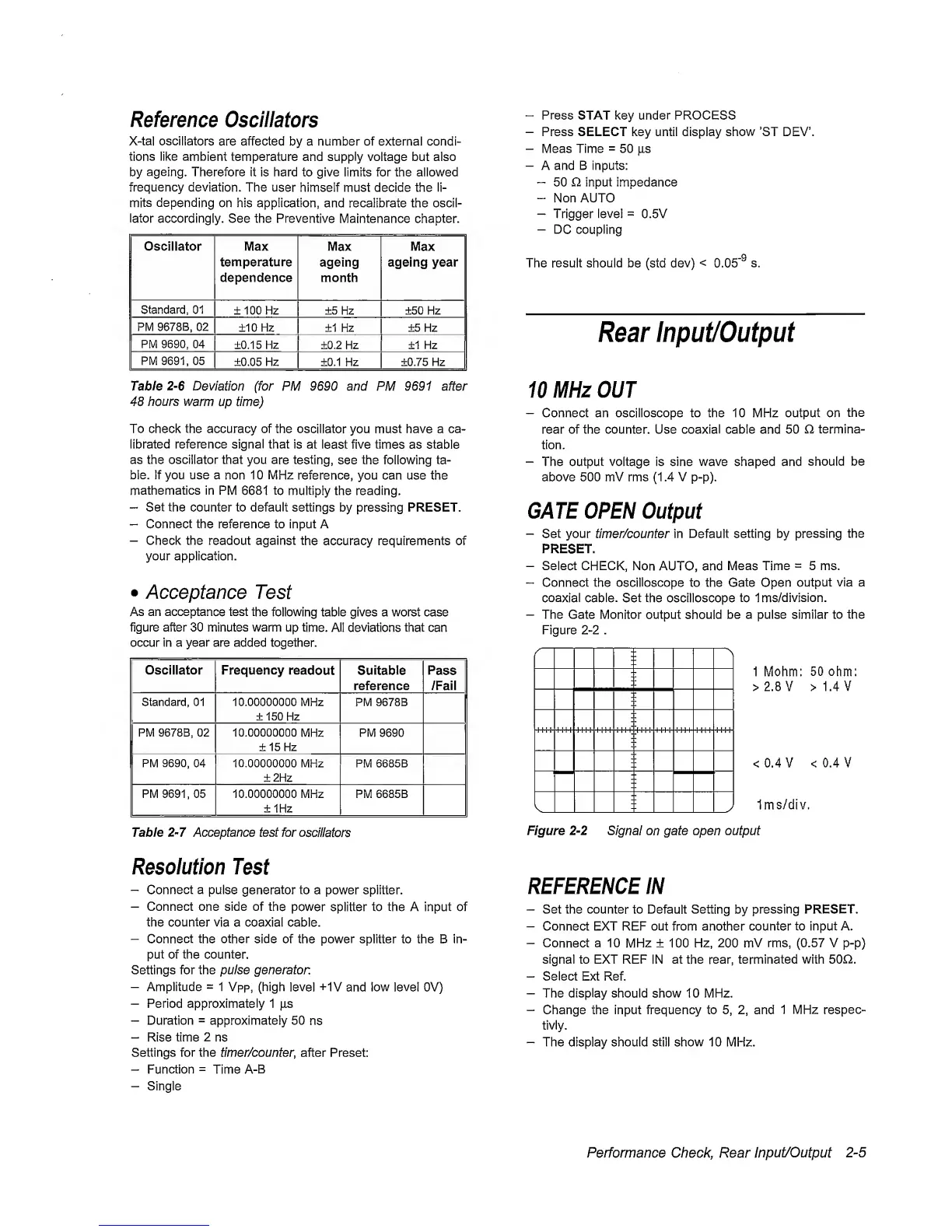
GATE OPEN Output
-
Set your timer/counter in Default
setting
by
pressing the
PRESET.
-
Select CHECK,
Non AUTO, and
Meas
Time
=
5 ms.
~
Connect the oscilloscope to the Gate Open
output via a
coaxial cable. Set the oscilloscope
to
Ims/division.
-
The Gate Monitor
output should be
a pulse similar to the
Figure
2-2
.
1 Mohm:
50
ohm:
>2.8V >1.4V
<0.4V <0.4V
Ims/div.
Figure
2-2
Signal on
gate open output
REFERENCE IN
-
Set the counter to Default Setting
by
pressing PRESET.
-
Connect EXT REF out from another counter to input A.
-
Connect
a 10
MHz
± 100
Hz, 200 mV
rms,
(0.57
V
p-p)
signal to EXT REF
IN
at the rear, terminated with 50Q.
-
Select Ext Ref.
-
The display should show
10
MHz.
-
Change the input frequency to
5, 2,
and
1
MHz
respec-
tivly.
-
The display should still show 10 MHz.
Performance Check, Rear
Input/Output
2-5
 Loading...


