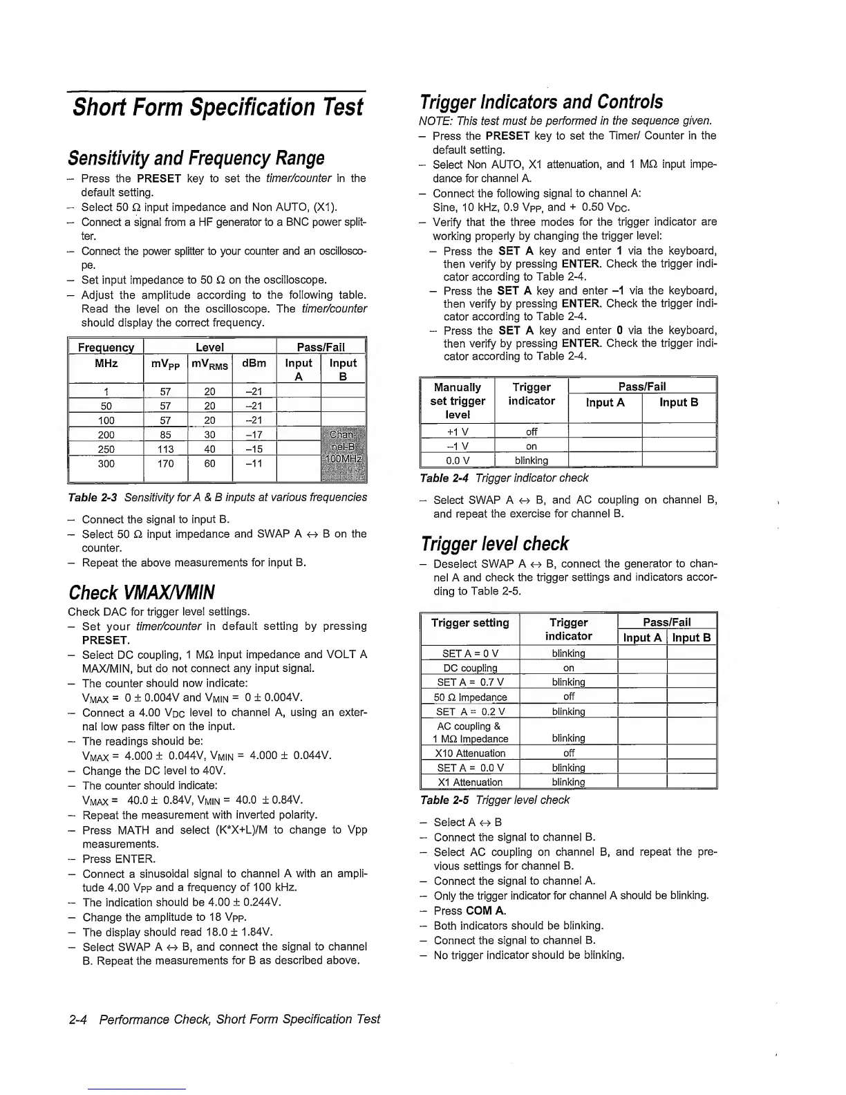
Short
Form
Specification
Test
Sensitivity and
Frequency
Range
-
Press the PRESET key
to
set
the timer/counter in the
default
setting.
“
Seiect 50 Q
input
impedance and Non
AUTO,
(X1).
“
Connect a signal from a HF
generator
to a
BN
C
power
split-
ter.
—
Connect the power splitter to your
counter
and an oscillosco-
pe.
—
Set
input impedance
to 50 Q, on the oscilloscope.
-
Adjust the amplitude according
to
the following table.
Read the
level on
the oscilloscope. The timer/counter
should display the
correct
frequency.
Frequency
Level Pass/Fail
|
MHz mVpp
dBm input
A
Input
B
1
57
20
-21
50
57
20
-21
100 57
20
-21
200 85
30
-17
Chan-
lOOMHzi
250 113 40
-15
300 170
60
-11
Tabie
2-3
Sensitivity
forA&B
inputs at various frequencies
“
Connect
the signal to
input
B.
-
Select 50 O
input
impedance
and SWAP A B on the
counter.
-
Repeat the above
measurements for input B.
Check
VMAX/VMiN
Check DAC for
trigger level
settings.
-
Set your
timer/counter in
default
setting by pressing
PRESET.
-
Select DC
coupling,
1 input
impedance
and VOLT A
MAX/MIN,
but
do not connect any
input signal.
-
The counter
should now
indicate:
Vmax
=
0 ±
0.004V and
Vmin
=
0 ± 0.004V.
-
Connect a
4.00
Vdc
level
to channel A, using an exter-
nal low pass
filter on the
input.
-
The
readings
should
be:
Vmax
=
4.000
± 0.044V,
Vmin
=
4.000 ± 0.044V.
-
Change
the DC
level to 40V.
-
The counter
should indicate:
Vmax
-
40.0
±
0.84V,
Vmin
=
40.0 ± 0.84V.
-
Repeat the
measurement
with inverted polarity.
-
Press MATH
and select
(K*X+L)/M
to change to Vpp
measurements.
-
Press ENTER.
-
Connect a
sinusoidal signal to
channel
A with an ampli-
tude 4.00
Vpp
and a frequency of 100
kHz.
“
The indication
should be 4.00
± 0.244V.
-
Change
the
amplitude to 18 Vpp.
-
The
display
should
read 18.0 ±
1.84V.
-
Select
SWAP A
4^ B, and
connect
the signal to channel
B. Repeat the
measurements
for B as described above.
Trigger
indicators
and
Controis
NOTE: This test must
be performed in the
sequence given.
-
Press
the PRESET key to
set
the Timer/ Counter in
the
default
setting.
“
Select
Non AUTO, XI
attenuation,
and 1 MQ, input
impe-
dance for
channel A.
-
Connect the
following
signal to channel A:
Sine,
10 kHz, 0.9 Vpp,
and
+
0.50
Vdc-
-
Verify
that the three
modes
for the trigger
indicator
are
working
properly
by changing the
trigger level:
-
Press
the SET A key
and enter 1 via
the
keyboard,
then
verify
by pressing
ENTER.
Check the trigger indi-
cator
according to Table
2-4.
-
Press the
SET
A key
and enter
-1
via the keyboard,
then verify by
pressing ENTER. Check
the trigger indi-
cator
according to
Table
2-4.
“
Press
the SET A key and
enter 0 via the keyboard,
then
verify
by pressing
ENTER.
Check the trigger indi-
cator
according to Table
2-4.
Manually
set
trigger
level
Trigger
indicator
Pass/Fail
Input A
Input B
+1 V off
-1
V on
0.0 V blinking
Table
2-4
Trigger
indicator check
-
Select SWAP A
B, and AC coupling on
channel
B,
and repeat
the exercise for channel
B.
Trigger
ievei
check
-
Deselect
SWAP
A
4-^
B, connect the
generator
to chan-
nel A
and
check the trigger
settings and indicators accor-
ding
to Table
2-5.
Trigger setting
Trigger
indicator
Pass/Fail
Input
A
Input B
SET A
=
0
V blinking
DC coupling
on
SETA= 0.7
V blinking
50 £2 impedance
off
SET A
=
0.2
V
blinking
AC coupling &
1 M£2
Impedance
blinking
XI 0 Attenuation
off
SETA=
0.0 V blinking
XI Attenuation
blinking
Table
2-5
Trigger
ievei check
-
Select A
^
B
“
Connect
the signal to channel
B.
-
Select
AC coupling on
channel B, and
repeat
the pre-
vious
settings for channel
B.
-
Connect the
signal to channel A.
-
Only
the trigger
indicator
for
channel A should be
blinking.
“
Press
COM A.
-
Both
indicators should be
blinking.
-
Connect
the
signal to channel
B.
-
No trigger
indicator
should be blinking.
2-4
Performance
Check, Short Form
Specification
Test
 Loading...


