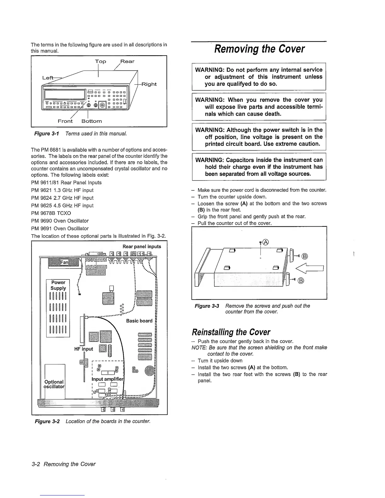
The
terms
in the following
figure are
used in aii descriptions
in
this
manual.
Figure
3-1
Terms used in this manual.
The
PM
6681
is avaiiabie with a
number
of options and acces-
sories. The iabels on the rear panel of
the
counter identify the
options and accessories included, if there are
no
iabeis, the
counter contains
an
uncompensated crystal
oscillator
and no
options.
The
following
labels exist:
PM 9611/81 Rear Panel
Inputs
PM
9621
1.3 GHz HF
input
PM 9624 2.7 GHz HF input
PM 9625 4.5 GHz HF Input
PM
9678B
TCXO
PM
9690
Oven
Oscillator
PM 9691
Oven Oscillator
The
location of
these optional parts is
illustrated
in Fig.
3-2.
Removing the
Cover
WARNING: Do not
perform any internal
service
or adjustment of
this
instrument unless
you
are qualifyed to do so.
WARNING: When you
remove the
cover you
will expose
live parts
and accessible
termi-
nals
which can cause death.
WARNING: Although the
power switch is in
the
off
position,
line voltage is
present
on the
printed circuit board. Use
extreme
caution.
WARNING: Capacitors
inside the instrument
can
hold
their charge
even if the
instrument
has
been separated
from all voltage sources.
—
Make
sure
the power cord is disconnected
from
the counter.
—
Turn the counter
upside
down.
—
Loosen the
screw
(A) at the bottom and the two
screws
(B) In
the rear
feet.
-
Grip
the front panel and gently push
at
the rear.
-
Pull the
counter out of the cover.
Figure
3-3
Remove the screws and push
out the
counter from the
cover.
Reinstalling
the
Cover
“
Push the counter gently back in
the
cover.
NOTE:
Be sure that the screen shielding on
the
front make
contact
to the cover.
”
Turn
it
upside down
-
Install
the
two screws (A) at the bottom.
-
Install the
two
rear
feet with the screws (B) to the
rear
panel.
3-2
Removing the
Cover