Fan
-
Disconnect
the
power
cable.
-
Remove
the cover from the counter.
-
Remove the two
screws (A) and nuts (B) from the fan.
-
Disconnect
the
fan cable from J 18.
—
When reinstalling
the fan, be sure that the air-flow arrow
on the fan points to the rear of the
counter
and that the
black wire is
oriented toward the power module.
Figure
3-4
The fan
is fastened with four screws and
nuts.
PM
9621,
PM
9624
or
PM
9625
HF
Input
-
Disconnect
the power cable.
-
Remove the cover from the
counter.
-
Disconnect the cable
from the
mini-coax connector (A)
on the HF input.
-
Press the clips (B) apart and
lift the HF input pea
straight up
and
out.
-
When
installing
the HF input, make sure that the
connec-
tor
pins fit exactly in the holes
in
the connector
housing
(C).
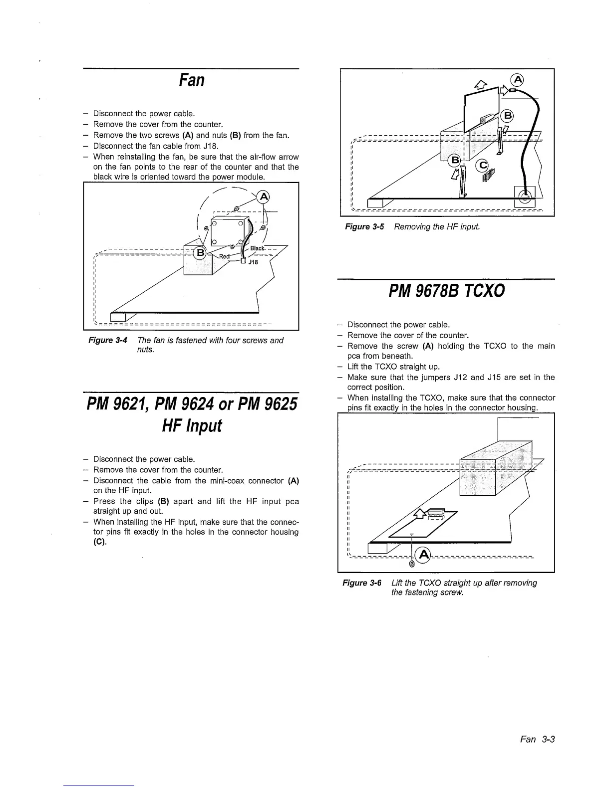
Figure
3-5
Removing the HF Input.
PM
9678B
TCXO
~
Disconnect the power cable.
-
Remove
the cover of the counter.
-
Remove
the screw (A) holding
the TCXO to the main
pea
from beneath.
-
Lift
the TCXO straight up.
-
Make
sure that the jumpers J12
and
J15 are set in the
correct
position.
-
When
installing the TCXO, make sure
that the
connector
pins fit
exactly
in
the
holes in
the
connector housing.
Fan
3-3