+9
V
Used unregulated.
At
stand-by,
the regulated supply
voltages
except
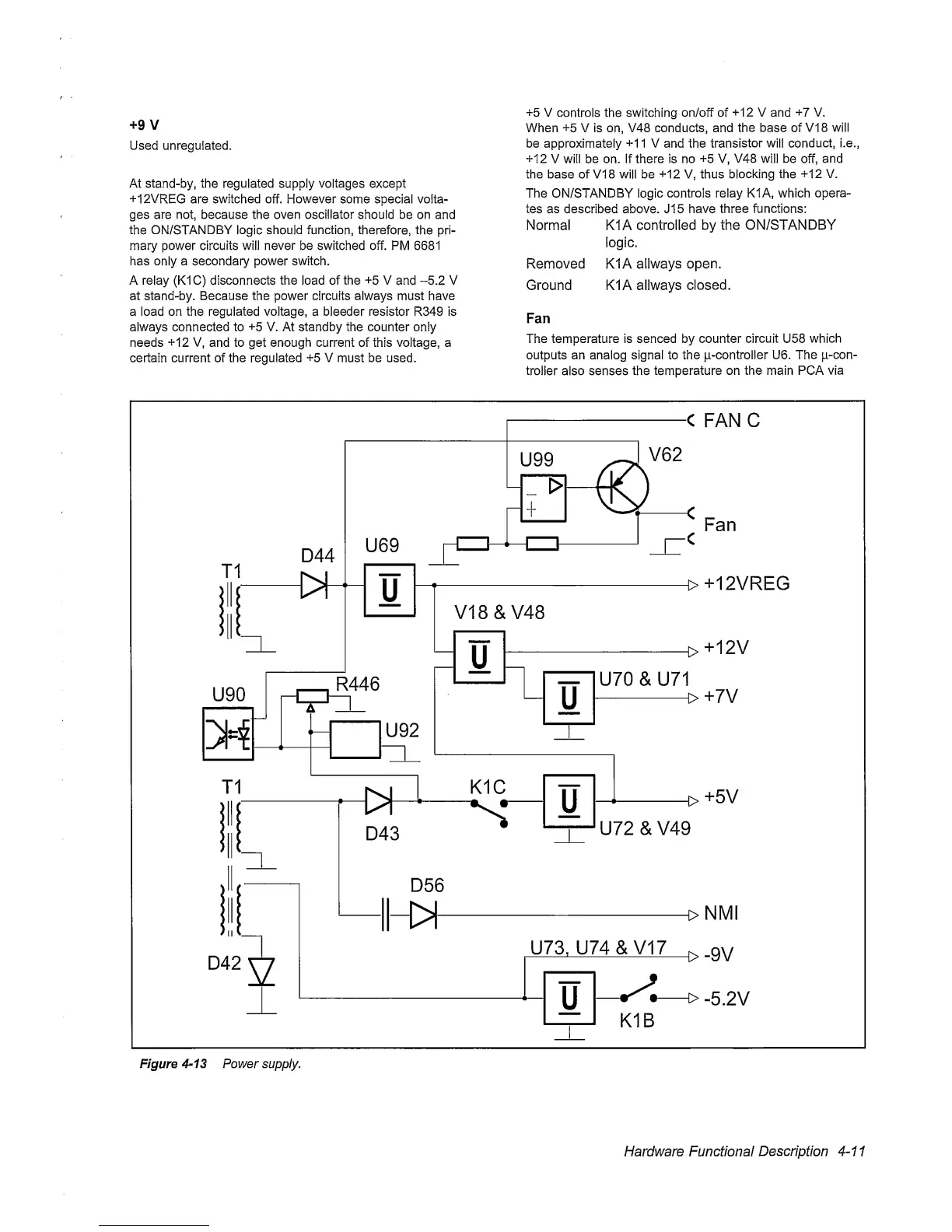
+12VREG are switched off. However some special volta-
ges are not, because the oven oscillator should be on and
the ON/STANDBY logic should
function,
therefore, the
pri-
mary power circuits will never be switched off. PM 6681
has only a secondary power switch.
A relay (K1C) disconnects the load of the
+5
V and
-5.2
V
at stand-by. Because the power circuits always must have
a load on the regulated voltage, a bleeder resistor R349 is
always connected
to
+5
V.
At
standby the counter
oniy
needs
+12
V, and to get enough current of this voltage, a
certain current of
the regulated
+5
V must be used.
+5
V
controls
the switching
on/off of
+12
V
and
+7
V.
When
+5
V is
on,
V48 conducts, and
the
base
of
VI
8 will
be approximately
+1
1 V and the
transistor will
conduct, i.e.,
+12
V will be on. If there is no
+5
V,
V48
will
be off,
and
the base of VI 8 will be
+12
V, thus blocking the
+12
V.
The
ON/STANDBY
logic
controls relay K1A, which
opera-
tes as described above. J15
have
three functions:
Normal K1A controlled
by the ON/STANDBY
logic.
Removed K1A allways
open.
Ground K1A allways
closed.
Fan
The temperature is senced by counter
circuit
U58
which
outputs an analog signal to the p-controller
U6.
The
p-con-
trolier
also senses
the
temperature on the main PCA
via
Hardware Functional
Description
4-11