Counter
Circuits
The PM 6681
measuring logic consists
of two ASIC’s: One
high speed
bipolar
ECL
circuit and
one
CMOS circuit The
bipolar
SMTC,
(U56) contains the
measuring control
functions, high speed
counters and some
analog
parts
used to
increase
the time resolution.
The CMOS ASMTC,
(U58)
consists of two counter
chains for the measurement
and logic for measuring
the expanded interpolator pulses.
It also contains two
programmable
mono flip flops
(100
ns
resolution),
an oscillator and an
external
reference input,
(see Figure 4-16).
Interpolator
The
bipolar
circuit has a
small
analog part. This part increa-
ses the
resolution in time and
frequency measurements by
means of an analog
interpolator.
An analog interpolator is
basically a
capacitor
charged and
discharged with different
currents
(ratio approximately
400).
A small error pulse is
extended
with the ratio
of
these
currents, (see Figure 4-14).
Figure 4~1G
The
interpolator expands
the error
pulse
400
times.
ked with 100 MHz when the signals IPA and IPB are pre-
sent.
After the counter circuit the signal is fed to OQ0504,
U56, to
be measured.
Timing
The following timing diagram (Figure
4-17)
shows
a num-
ber of measurement
signals
for a
frequency measurement
of
11
periods. This measurement is started directly when
reset is released. The measurement start can
be
controlled
in a much
more
detailed
manner. GET and arming
delays
(event
or time) can be used to qualify the measurement
start.
Qualifying the stop can be done in the same advan-
ced way. The basic
method
is to send
a
Measurement
STOp (MSTO) signal to
the circuits
via the
\iC
interface.
This signal
cannot
be viewed externally.
The length of IPA and IPB is not correctly viewed (approxi-
mately 3 to
7
s).
Clock
Reset
"1
input sign.
IPB
XCY
-//-
-//-
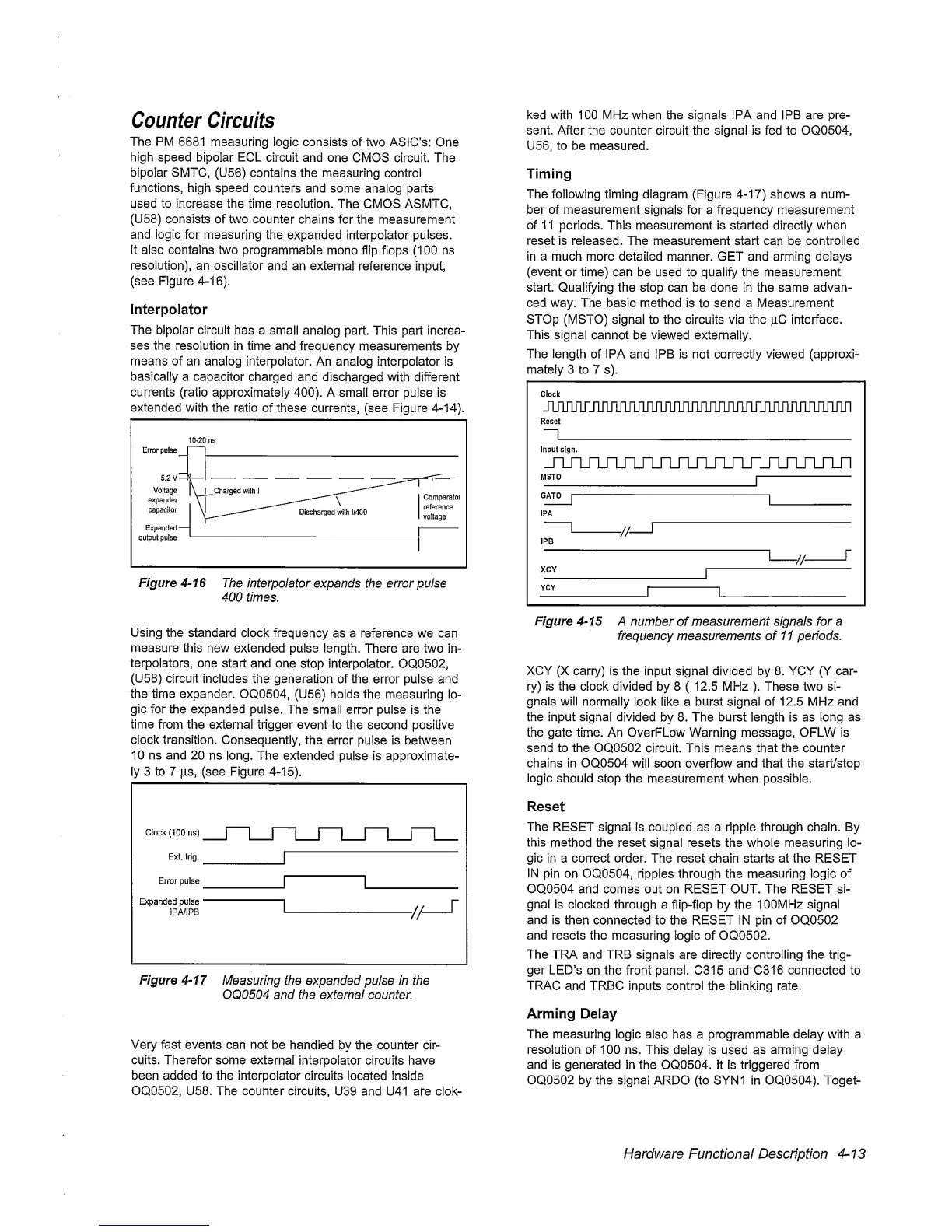
Using the
standard clock frequency
as a reference we can
measure
this
new extended pulse length.
There are
two
in-
terpolators,
one start and one
stop
interpolator. OQ0502,
(U58) circuit
includes the generation
of
the
error pulse and
the time expander.
OQ0504, (U56) holds
the
measuring lo-
gic for the expanded
pulse. The small error pulse
is
the
time
from
the
external trigger event
to the
second positive
clock
transition.
Consequently, the
error
pulse is between
10 ns and
20
ns long. The extended
pulse is approximate-
ly 3 to
7
ILLS,
(see Figure
4-15).
Figure
4-17
Measuring the expanded
pulse In the
OQ0504 and the
external counter.
Very fast events can not
be handled by the counter cir-
cuits. Therefor some externa!
interpolator circuits have
been added to the interpolator
circuits located inside
OQ0502, U58. The counter circuits,
U39 and U41 are clok-
Figure
4-15
A number of measurement signals for a
frequency
measurements of
11
periods.
XCY
(X carry) is the input signal divided by 8. YCY (Y car-
ry) is the
clock
divided
by
8
(
12.5 MHz
).
These two si-
gnals will
normally look like a burst signal of
12.5 MHz
and
the input signal
divided
by 8. The burst length is as long
as
the gate time.
An OverFLow
Warning
message, OFLW is
send to the OQ0502
circuit. This means
that the counter
chains in OQ0504
will
soon
overflow and
that the start/stop
logic
should
stop the measurement when possible.
Reset
The RESET
signal is coupled as a ripple through chain.
By
this
method
the reset signal resets the whole measuring lo-
gic in a correct order. The reset chain starts at the RESET
IN
pin on OQ0504, ripples through the measuring logic of
OQ0504 and comes out on RESET OUT. The RESET si-
gnal is clocked through
a flip-fiop by the
100MHz signal
and is
then
connected to the RESET IN pin of OQ0502
and resets the
measuring
logic of OQ0502.
The TRA and TRB
signals
are
directly
controlling the trig-
ger LED’s
on
the
front panel. C315 and C316
connected
to
TRAC
and TRBC inputs control the blinking
rate.
Arming
Delay
The measuring logic
also
has a
programmable
delay with a
resolution of 100 ns.
This
delay is used
as
arming
delay
and
is generated in the OQ0504. it is
triggered
from
OQ0502 by
the
signal ARDO (to SYN1 in OQ0504). Toget-
Hardware Functional Description
4~13
 Loading...


