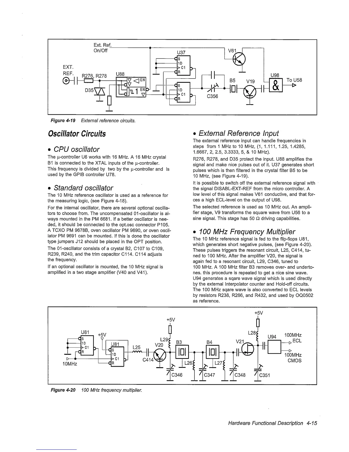
Figure
4-19
Externa! reference
circuits.
Oscillator Circuits
•
CPU
oscillator
The
ii-controiler
U6
works
with 16 MHz. A
16 MHz crystal
B1
is connected to the XTAL
inputs of the
p-controller.
This frequency is divided by
two by the
p-controller
and is
used by the GPIB
controller
U78.
•
standard
oscillator
The 10 MHz
reference oscillator is
used
as a reference for
the measuring logic, (see
Figure 4-18).
For the interna!
oscillator,
there are several
optional
oscilla-
tors to
choose
from. The
uncompensated
01
-oscillator is al-
ways mounted
in the PM 6681. If a better
oscillator is nee-
ded, it should be
connected
to the opt.osc
connector
PI 05.
A TCXO PM 9678B, oven
oscillator PM
9690,
or oven
oscil-
lator
PM 9691 can be mounted,
if
this
is done the oscillator
type
jumpers
J12 should be placed
in the OPT position.
The 01-oscillator
consists of a crystal B2, C107
to C109,
R239, R240, and
the trim
capacitor Cl 14.
Cl
14 adjusts
the frequency.
If an optional oscillator is
mounted,
the 10 MHz
signal
is
amplified in a two stage
amplifier
(V40
and V41).
•
External Reference
Input
The external reference input can handle frequencies in
steps from 1 MHz to 10 MHz,
(1,
1.111,
1.25,
1.4285,
1.6667,
2,
2.5,
3.3333,
5,
& 10 MHz).
R276, R278, and
D35
protect the input. U88 amplifies the
signal and
make
nice
pulses out of it. U37 generates short
pulses
which
is then
filtered
in the crystal filter B5 to be
10
MHz,
(see Figure
4-19).
It is
possible to switch
off the external reference signal with
the signal
DISABL-EXT-REF
from the micro controller. A
low level
of
this signal
makes V61 conductive, and that for-
ces a high ECL-level
on the output
of U98.
The selected reference is
used as
10
MHz
out. An ampli-
fier stage, V9 transforms the square wave
from U56 to a
sine signal.
This
stage
has 50 O. driving capabilities.
•
100 MHz
Frequency
Multiplier
The
10 MHz reference signal is fed to the flip-flops U81,
which generates short negative pulses, (see Figure
4-20).
These pulses triggers the resonant circuit, L25, C414,
tu-
ned
to
100 MHz. After the amplifier V20, the signal is
again fed
to
a resonant circuit, L29, C346, tuned to
100 MHz. A
100 MHz filter
B3
removes
over- and underto-
nes. this procedure is
repeated to get a nice sine wave.
U94 generates a sqare
wave
signal which is used directly
by the external Interpolator
counter
and Hold-off circuits.
The 100 MHz sqare wave is also converted to ECL
levels
by resistors R238, R266, and R432, and used by
OQ0502
as reference.
Figure
4-20
100 MHz frequency multiplier.
Hardware
Functional
Description
4-15
 Loading...


