Level
detector
Prescaler
2.
7
GHz, PM 9624
C13, C16,
and
L6 form a filter
making the frequency
re-
sponse of the
signal to
the level
detector
diode GR7, the
same as the signal
to
IC2, (see Figure
4-30).
The detector voltage is
filtered
and fed to
IC3. Diode
GR15
prevents
the level from being
too
negative (IC3
is then lok-
ked).
The first stage in 1C3
amplifies
the level
approximate-
ly 15
times
and the second stage
is a Schmitt trigger.
The
output from
the
Schmitt trigger can
block, via TS8, the ECL
output signal. A low output
signal from 1C3
pin 7 makes
TS8 conduct. The ECL output
signal will be
4.5
V.
If IC3
pin 7 is high, TS8 is not
conducting,
and the
output
signal
from TS7 is not blocked.
The Schmitt trigger
is controlled
from the first amplifier
in
1C3. If the level
on IC3 pin
3
(de-
tected level) is lower
than the reference
ievel
on IC3 pin 2
(an
HF signal with
sufficient level
present), ICS pin 1 is
low
and
the Schmitt trigger output
is high, thus not
blocking
the
ECL output
signal. The reference
level
on 1C3 pin 2 Is set
by trim-potentiometer R30.
GR8,
GR9, and R28
form a
temperature compensation
circuit, to
compensate
for the
temperature behavior
of the detector
diode
GR7. Forte-
sting purposes, the level
detection can
be overruled
by the
signal TEST
GO. A high level makes
TS10 conduct, and
that
enables the ECL output
signal,
despite the
HF input si-
gnal amplitude. The ECL
output
signal can also
be swit-
ched off, despite the level
detection. A
high level
on signal
NOT C makes TS9
conduct and thus
makes the level to
TS8 low. TS8 makes
the
ECL output
signal
+4.5
V.
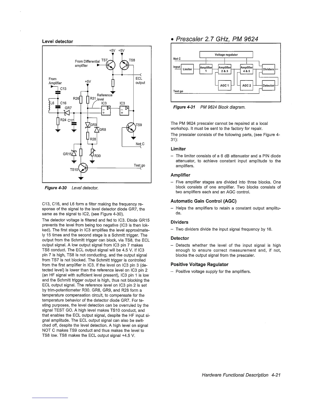
Figure
4-31
PM 9624
Block diagram.
The PM
9624
prescaler
cannot be repaired at a local
workshop.
It must
be sent to the factory for repair.
The prescaler consists of the following parts,
(see Figure
4-
31):
Limiter
-
The limiter
consists
of a 6 dB attenuator and a PIN diode
attenuator,
to achieve
constant input amplitude to the
amplifiers.
Amplifier
-
Five amplifier stages
are
divided
into three blocks. One
block consists of one
amplifier.
Two blocks consists of
two amplifiers
each
and an AGC control.
Automatic Gain Control
(AGC)
-
Helps the amplifiers to
retain a constant output amplitu-
de.
Dividers
-
Two
dividers divide
the input signal frequency by 16.
Detector
-
Detects
whether the level of the
input
signal
is high
enough
to ensure correct measurement and,
if
not,
blocks
the output signal from the
prescaler.
Positive Voltage
Regulator
“
Positive voltage supply
for the amplifiers.
Hardware
Functional Description
4-21
 Loading...


