Optional
Units
HF Inputs
There
is
a
choice of three
different optional HF inputs;
PM
9621,
PM
9624,
and PM 9625,
The inputs are all
mounted
on the
same
place on the main board,
to
the
right
of
the input
amplifier. They
are
connected to
PI
07,
and
only one prescaler at a
time can
be mounted. In BU7 there
are 3 ID pins.
Different
prescalers
have different
coding of
these pins. PM 9624 and PM
9625 are factory repair only,
due to the need
of
Instrumentation for high
frequencies.
•
Prescaler 1.3
GHz, PM 9621
Figure
4^26
PM
9621 Block diagram.
The frequency
range for the
prescaler
is 70 MHz to 1.3
GHz. To be able to be
handled
by the measuring logic in
the counter the frequency
is divided by 256.
The input
is
AC-coupled
and
the input impedance is
50^2 nominal. Five
main blocks
makes the prescaler:
Limiter, amplifier, divider,
ECL output, and
ievel
detector, (see Figure
4-26).
Limiter
The 6 dB
attenuator
(R1 to R1
1)
keeps the VSWR \o\n for
all input levels,
even the PIN diodes have
low impedance,
(see Figure
4-27).
When the peak-to-peak level of
the
in-
put signal is
greater
than
the
sum of the
voltage
drops of
the Schottky
diodes
GR3 and GR4, the
charging
of capaci-
tor C4 starts.
Capacitor C4 filters the
voltage after the
Schottky diodes.
The
PIN diodes GR11
start
to conduct
when
the voltage is
lower than
approximately
-0.65
V.
More
current through the
diodes
means
lower
impedance.
This
means that the HF
voltage over GR1 1 is
constant.
R12
discharges C4 then the
input
level
decreases. LI
pre-
vents
capacitor C4 from
short-circuiting
the HF
signal.
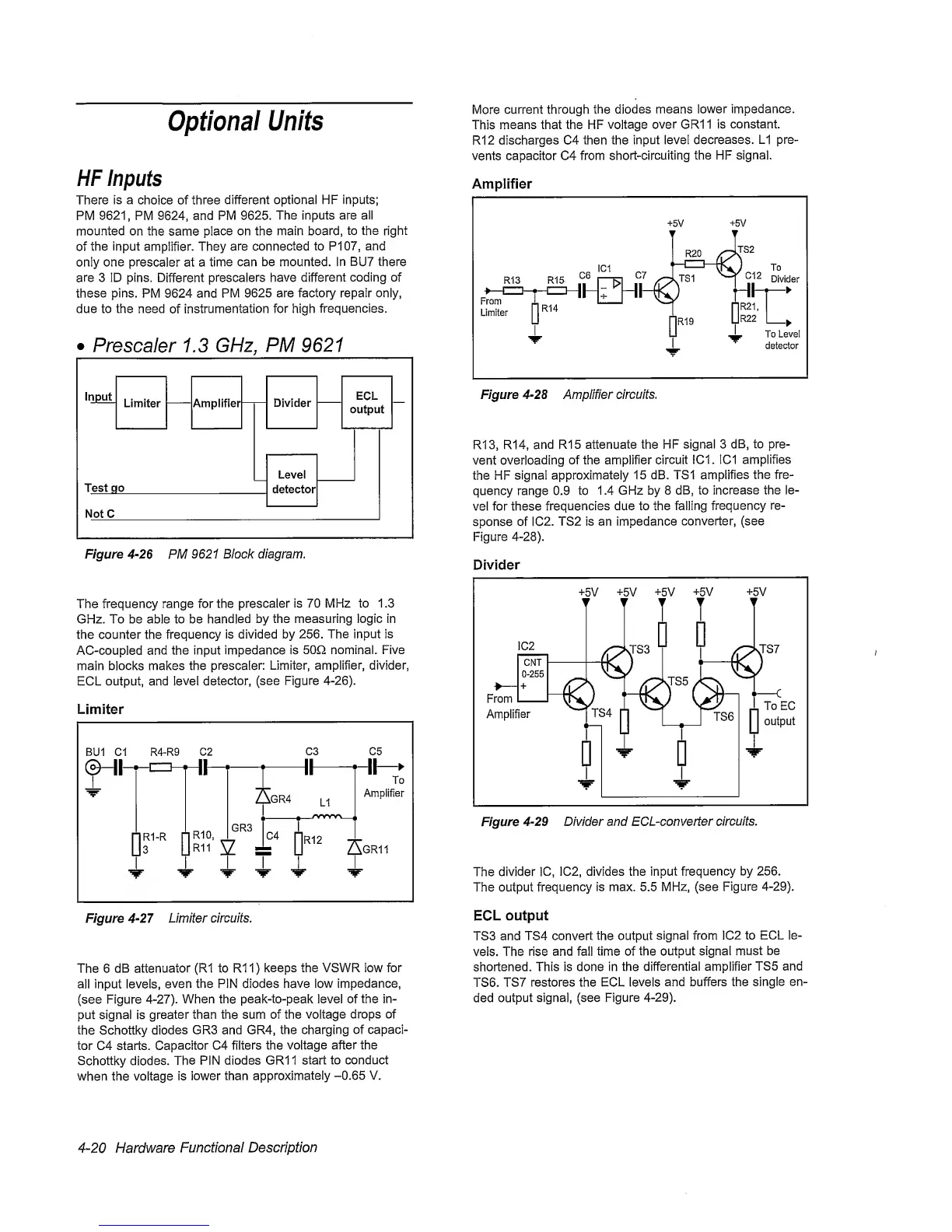
Amplifier
R13, R14,
and
R15
attenuate the HF
signal 3 dB, to pre-
vent
overloading
of the amplifier
circuit
IC1. 1C1 amplifies
the
HF
signal
approximately
15 dB. TS1
amplifies
the fre-
quency range 0.9 to
1.4
GHz by 8 dB, to
increase the le-
vel for these
frequencies
due to the falling
frequency re-
sponse of IC2.
TS2 is an impedance
converter, (see
Figure
4-28).
Divider
Figure
4-29
Divider and ECL-converter
circuits.
The
divider
1C, 1C2, divides the input
frequency
by 256.
The output
frequency
is max. 5.5 MHz, (see
Figure 4-29).
ECL
output
TS3
and TS4 convert
the output
signal from 1C2
to
ECL le-
vels. The rise
and fall time of
the
output signal must
be
shortened. This is done in the
differential amplifier
TS5
and
TS6.
TS7
restores the ECL
levels
and buffers the
single
en-
ded
output
signal, (see Figure
4-29).
4~20
Hardware
Functional
Description
 Loading...


