Troubleshooting
General
Quick Troubleshooting
The PM
6681
is a highly integrated
Timer/Counter
with de-
dicated
LSI counter circuits and
microcontrollers
that con-
trol the complete units. The
microcontroller
can help you
to
locate
faulty
parts by running test programs
and
generating
stable
signal patterns on the bus. If the
microcontroller
does not work or the
fault
is in
a part of the counter
that
cannot be accessed by
the microcontroller,
traditional
fault-
finding must be performed.
Where
to
Start
After reading
the safety instructions, continue
with
this Chapter
for
faultfinding
and repair instructions.
When
you have fixed
the instrument, always do
the Safety Inspection and
Test after
Repair, as
described
later in this Chapter. Then do
the checks
in Chapter
2,
Performance Check.
Recalibrate
if
required by
following the
adjustment instructions in
Chapter
6,
Calibration
Adjustments.
Logical
Levels
The PM
6681 contains
logic
of four families. The
levels for
these
families
are
listed
in
Table
5-2.
Positive
ECL
Negative
ECL
CMOS TTL
Supply voltage
+5 V
-5
V
+5
V
+5 V
Signal
ground
0 V 0
V 0 V 0 V
Input voltage
High,
ViH
>+3.9
V
>-1.1
V >+4V
>+2
V
Low,
ViL
<+3.5
V
<-1.5
V
A
+
<
A+
O
bo
Output
voltage
High,
VoH
>+4V
>-1
V
>+4.9
V
>+2.7
V
Low,
VOL
<+3.3
V
<-1.7
V
<+0.05 V
<+0.4
V
Bias ref. voltage,
Vbb
+3.7
V
-1.3
V
-
-
Table
5~2
Logical
levels.
Required
Test
Equipment
To be able to test the
instrument properly using
this manu-
al you will need the
equipment
listed in Table
5-3.
The list
contains not only
suggested Fluke test
equipment,
but also
the critical
parameter
specifications required if
you have in-
struments from
other
manufacturers.
Type
Performance
Model No
DMM
-
PM 2518 or 77
Oscilloscope 50
Mhz
2-channel PM
3050
Signal
generator 1300 MHz
6062A
BNC-BNC cables
-
-
Table
5-3
Required
test equipment
Operating
Conditions
Power
voltage must be in the range of
90 to 260 Vac.
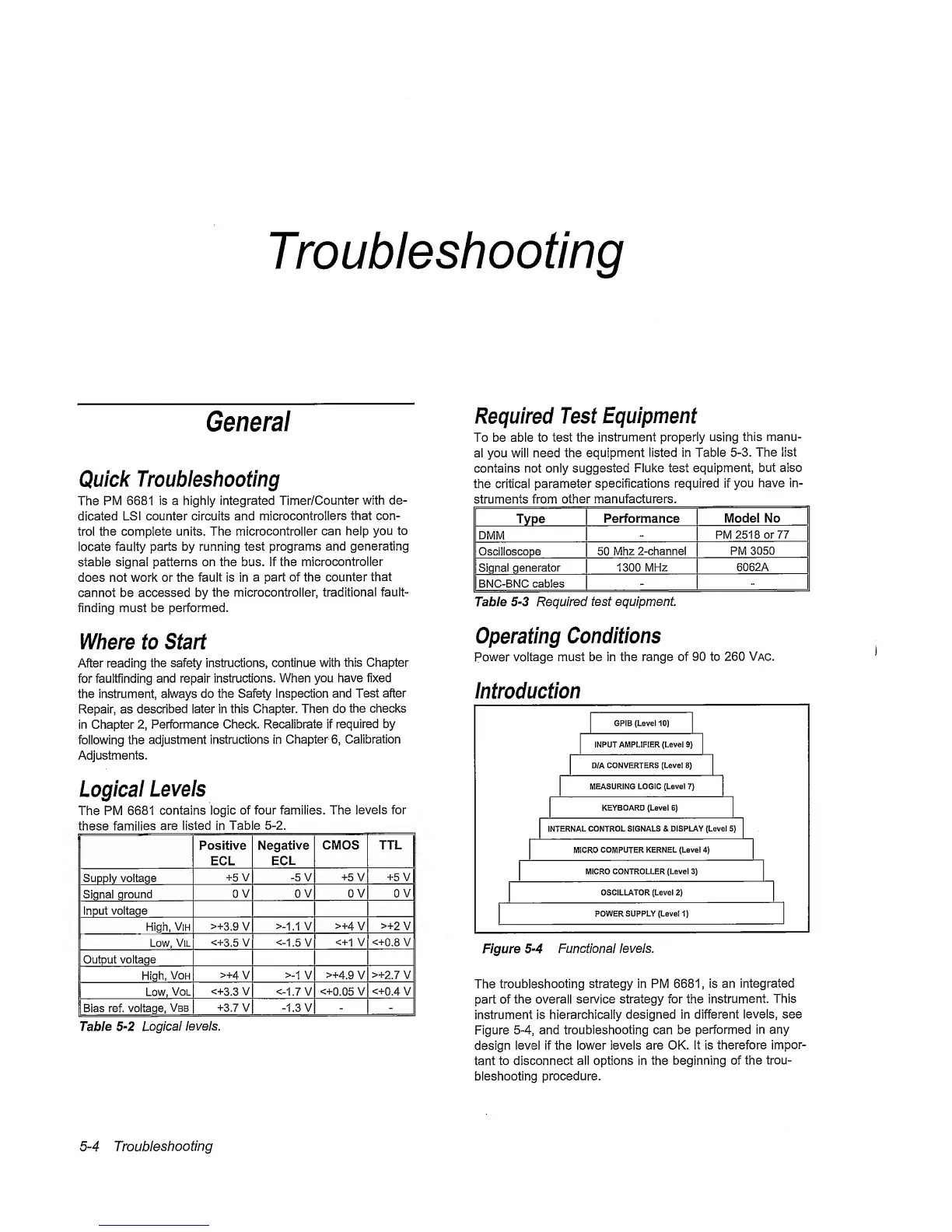
Introduction
I
GPIB(LeveMO)
|
INPUT AMPLIFIER
(Level
9}
D/A
CONVERTERS
[Level B}
MEASURING
LOGIC (Level
7)
KEYBOARD (Level
6)
INTERNAL
CONTROL SIGNALS & DISPLAY (Level
5)
MICRO
COMPUTER
KERNEL (Level
4)
MICRO CONTROLLER
(Level
3)
OSCILLATOR (Level
2)
POWER SUPPLY
(Level
1)
Figure
5-4
Functional
levels.
The
troubleshooting
strategy in PM
6681,
is an
integrated
part of the
overall
service strategy for the
instrument.
This
instrument is
hierarchically
designed in different
levels, see
Figure
5-4,
and troubleshooting can be
performed in any
design
level if the lower levels are OK.
It is
therefore
impor-
tant
to disconnect all options in
the beginning
of the
trou-
bleshooting procedure.
5-4
Troubleshooting
 Loading...


