Running
Test Programs
The service
functions are activated by connecting the two sol-
der points,
labeled
TEST,
J11 during startup, see Figure
5-6.
Figure
5-6
The
service
functions are activated
by con-
necting the two
soider
points, iabeied
TEST,
J1
1
during
startup.
-
Switch on the counter.
The ROM
test,
RAM
test,
and pC Kernel test runs automat-
ically. After the display test the test-program starts from
the beginning again. Use LOCAL/PRESET to step through
the different tests.
NOTE:
The
address test and dispiay test are described under
Levei 4 and Level
5
respectively,
but they cannot be
run before you have checked Level 6.
Text Function Level Exit
test r
0
ROM test 3 Automatically
test rA
RAM
test
3
Automatically
test Core
UC
Kernel test
3+4
LOCAL/PRESET
test relay
Control signal test 5 LOCAUPRESET
test buttn
Keyboard test 6 LOCAL/PRESET
test
Addr
.
Address test
4
LOCAL/PRESET
test ASIC
ASIC’s test
1 7
Automatically
test ASIC
ASIC’s test 2 7 LOCAL/PRESET
test dAC
DAC test
8 LOCAUPRESET
test ANALO
Analog out test 1 10 LOCAL/PRESET
85
Analog out test 2
10 LOCAL/PRESET
8888888888
Display test
5
LOCAUPRESET
Tabie
5-4
Test programs.
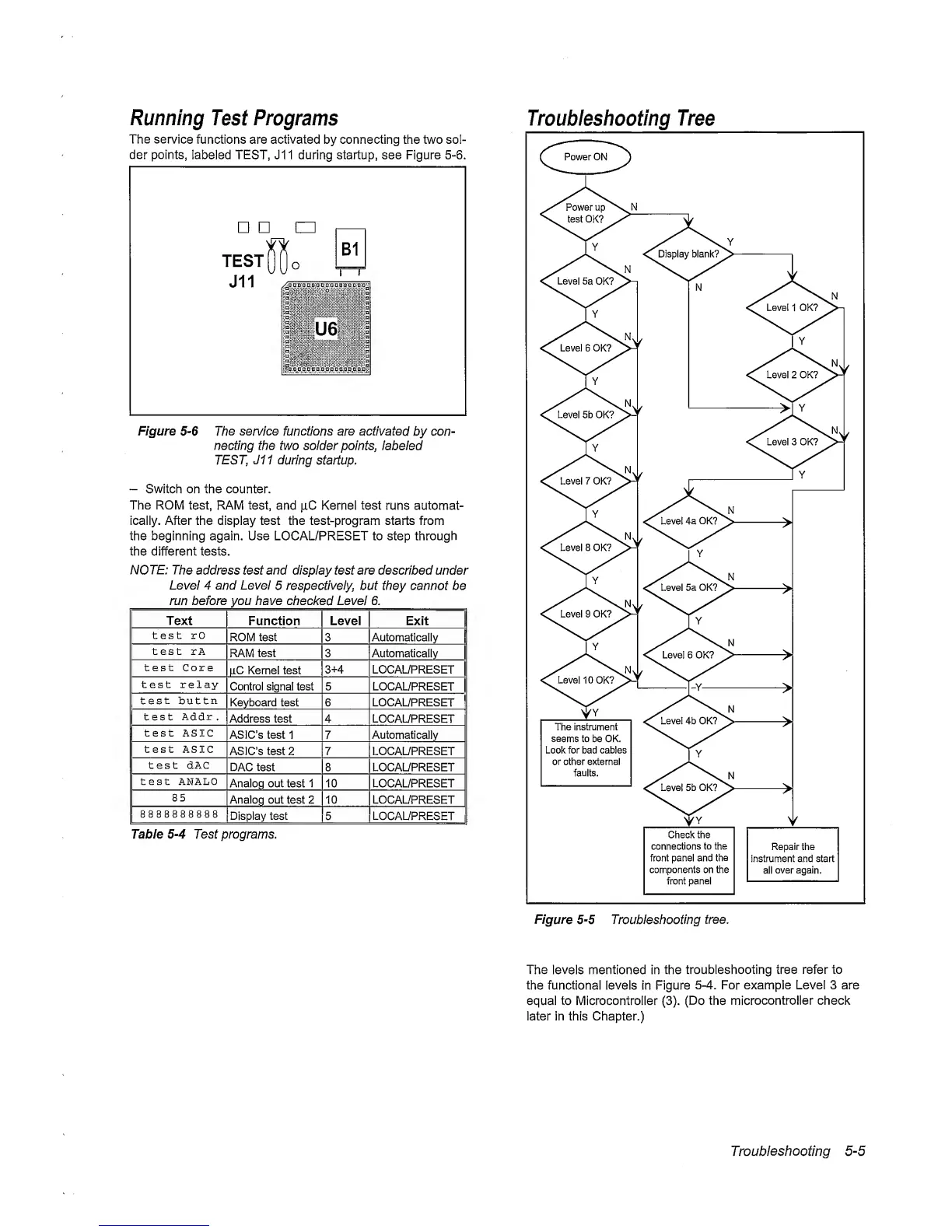
Troubleshooting Tree
The levels mentioned
in
the
troubleshooting tree refer to
the functional levels in Figure
5-4.
For example Level 3 are
equal to Microcontroller
(3).
(Do
the
microcontroller check
later in this Chapter.)
Troubleshooting
5-5