-
Check the "POWER ON" voltages according to Table
5-
6.
Use
L41
as ground.
Test points
Voltage
XI
5
+5.01
V±30 mV*
X16
-5.1
V+50
mV
X14
+7
V+100 mV
XI
7
+12
V ±100
mV
Table
5-6
Power-on voltages.
*NOTE: If the
+5
V voltage
is
outside the specification, ail ot-
her levels
will be wrong,
since
they are
based on the
+5
V
level.
If you find
any
fault, continue with traditional troubleshoo-
ting techniques and replace defective circuits. See also
Chapter
4,
Circuit
Descriptions, Power Supply.
Oscillator (Functional Level
2)
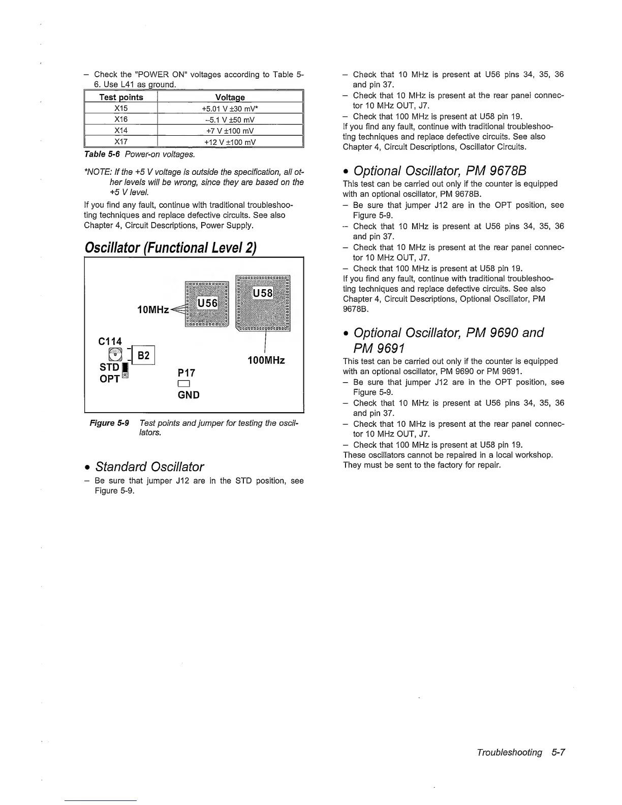
Figure
5-9
Test points and
jumper for testing
the oscil-
lators.
•
standard Oscillator
-
Be sure that
jumper J12 are in the
STD position,
see
Figure
5-9.
-
Check
that 10
MHz is
present at U56 pins
34, 35,
36
and
pin
37.
-
Check that 10
MHz
is
present
at the rear panel
connec-
tor
10 MHz OUT, J7.
-
Check that 100 MHz is present
at
U58
pin
19.
if
you find any fault, continue
with traditional
troubleshoo-
ting techniques and replace
defective
circuits.
See
also
Chapter
4,
Circuit Descriptions, Oscillator Circuits.
•
Optional Oscillator,
PM
9678B
This test can be carried out only if
the
counter
is
equipped
with an optional oscillator, PM 9678B.
-
Be
sure that jumper J12 are in
the OPT position,
see
Figure
5-9.
“
Check that 10 MHz is present at U56 pins
34, 35,
36
and
pin
37.
-
Check that 10 MHz
is
present at the rear pane!
connec-
tor
10 MHz OUT, J7.
-
Check
that
100 MHz
is
present at U58 pin 19.
If you find any fault, continue
with
traditional troubleshoo-
ting techniques and replace
defective circuits.
See also
Chapter
4,
Circuit Descriptions, Optional
Oscillator,
PM
9678B.
•
Optional Oscillator,
PM
9690
and
PM
9691
This test
can be carried
out only if the counter is
equipped
with an optional oscillator, PM 9690 or PM 9691.
-
Be
sure that jumper J12
are in the OPT position, see
Figure
5-9.
-
Check that 10 MHz is
present
at U56 pins
34, 35,
36
and
pin
37.
-
Check that 10 MHz is present at the rear panel
connec-
tor
10
MHz
OUT, J7.
-
Check that 100 MHz
is
present at U58 pin 19.
These oscillators cannot be repaired in a local
workshop.
They must be sent to the factory for repair.
Troubleshooting
5-7