Internal
Control Signals
and Display
(Functional
Level
5a)
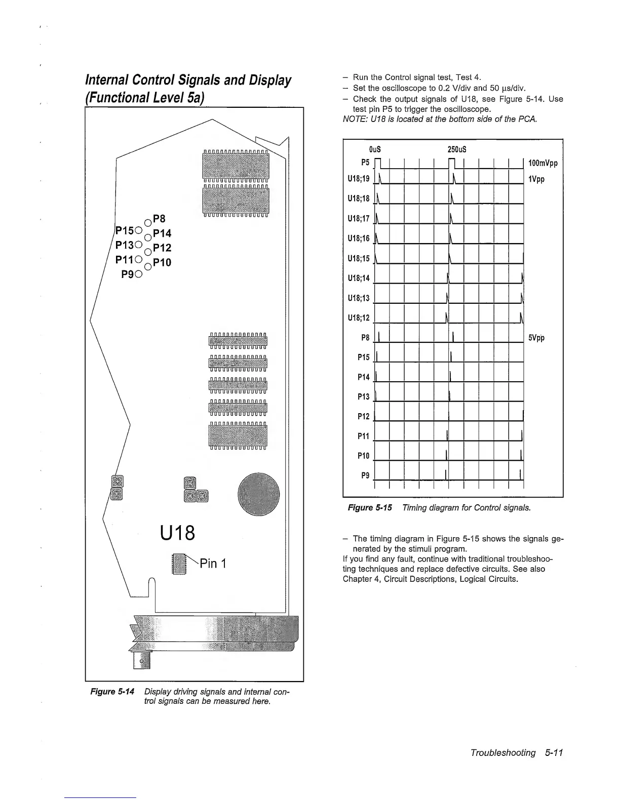
Figure
5-14
Display
driving signals
and internal con-
trol signals can
be measured
here.
—
Run the Control signal test,
Test
4.
—
Set the oscilloscope to 0.2 V/div and
50
ps/div.
—
Check the output signals of U18,
see
Figure
5-14.
Use
test
pin P5 to trigger the oscilloscope.
NOTE: U18 is located at the bottom
side
of the PCA.
Oi
P5
U18;19
^
U18;18
^
U18;17
U18;16
U18;15
U18;14
U18;13
^
U18;12
P8
,
P15
.
P14
P13
P12
P11
.
P10
P9
jS
FL
250u!
"L
3
lOOmVpp
IVpp
5Vpp
n n
I
k
k
k
!
k
1
k
n
k
1
rn
n
rn
Figure
5-15
Timing
diagram for Control signals.
-
The timing diagram in Figure
5-15
shows the signals ge-
nerated by the
stimuli program.
If you find
any
fault, continue
with
traditional troubleshoo-
ting techniques and
replace
defective circuits. See also
Chapter
4,
Circuit Descriptions, Logicai
Circuits.
Troubleshooting
5-11