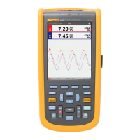
Do you have a question about the Fluke ScopeMeter 125B and is the answer not in the manual?
Identifies hazardous conditions and procedures that are dangerous to the user.
Information on Li-ion batteries, charging, and status.
Restores the Test Tool to the factory default settings.
Instructions for setting up specific measurement probes.
Captures and freezes a stable main reading on the display.
Performing a single shot to catch single events.
Determines when the Test Tool starts the waveform trace.
Optimizes trigger level and slope manually for waveform capture.
Measures amplitude, high/low values, or overshoot of a waveform.
Measures time difference and voltage difference between two markers.
Simultaneously shows voltage and current signal for initial impression.
Indicates status of OSI model Physical Layer for bus types.
Procedure for performing fieldbus measurements.
Sets parameters for recording meter measurements over time.
Logs meter readings as a graph or trend-line on screen.
Captures and stores waveforms for long memory records.
Shows all waveform data as a long waveform of each active input.
Procedure to save screen, waveform, and setup data.
Procedure and safety precautions for replacing the battery.
Guidelines for proper grounding to avoid problems.
Functions like Normal, Smooth, Envelope, and Auto Set.
Automatic adjustments for amplitude, time base, trigger levels.
Accuracy of measurements for dual input meter.
Specifications for power measurements on the 125B model.
Specifications for meter and waveform recording.
Operating and storage temperature, humidity, and altitude.
EMC compliance standards and classifications.
| Model | 125B |
|---|---|
| Brand | Fluke |
| Bandwidth | 40 MHz |
| Input Channels | 2 |
| Resolution | 320 x 240 pixels |
| Operating Temperature | 0 °C to +50 °C |
| Storage Temperature | -20 °C to +60 °C |
| Warranty | 3 years |
| Display Type | LCD |
| Display Size | 5.7 inches |
| Battery Life | 7 hours |
| Battery Type | Li-Ion |
| Connectivity | USB |
| Harmonics Analyzer | Yes |
| Bus Health Mode | Yes |
| Power Measurements | Yes |


 Loading...