EasyManua.ls Logo

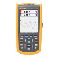
Fluke ScopeMeter 199C User Manual

Fluke ScopeMeter 199C
63 pages
To Next Page IconTo Next Page
Page #1 background imageLoading...
Page #1 background image
Fluke 19xB-19xC-2x5C
ScopeMeter
models 192B,196B,199B,192C,196C,199C,215C,225C
Service Manual

Table of Contents

Question and Answer IconNeed help?

Do you have a question about the Fluke ScopeMeter 199C and is the answer not in the manual?

Fluke ScopeMeter 199C Specifications

General IconGeneral
Bandwidth200 MHz
Sample Rate2.5 GS/s
Channels2
Battery LifeUp to 4 hours
Vertical Resolution8 bits
Timebase Range5 ns/div to 100 s/div
Input CouplingAC, DC, GND
Harmonics AnalyzerYes
Power Quality MeasurementsYes
Vertical Sensitivity2 mV/div to 100 V/div
DisplayColor LCD
Input Impedance1 MΩ
Operating Temperature0 °C to +50 °C
Maximum Input Voltage400 V (DC + AC peak)

Summary

Safety Instructions

Introduction

Overview of safety instructions for the test tool.

Safety Precautions

Essential procedures for correct and safe use of the test tool.

Caution and Warning Statements

Definitions and explanations of caution and warning statements.

Symbols

Explanation of symbols used on the test tool and in manuals.

Impaired Safety

Procedure when safety of the test tool is likely impaired.

General Safety Information

General safety guidelines for handling and servicing the tool.

List of Replaceable Parts

Introduction

Introduction to the chapter on replaceable parts.

How to Obtain Parts

Instructions on how to order replacement parts.

Final Assembly Parts

List of parts for the final assembly of the test tool.

Main PCA Unit Parts

List of parts for the main PCA unit of the test tool.

Accessories

List of standard and optional accessories for the test tool.

Performance Verification

Introduction

Introduction to the performance verification procedures.

Equipment Required For Verification

List of equipment needed for performance tests.

General Instructions

General guidelines to follow for all performance tests.

Operating Instructions

Instructions on how to operate the test tool for verification.

Display and Backlight Test

Procedure to test the display and backlight functionality.

Scope Input A&B Tests

Procedures for verifying the accuracy of scope inputs A and B.

External Trigger Level Test

Procedure to test the external trigger level functionality.

Meter (DMM) Tests

Procedures for verifying the accuracy of DMM measurements.

Probe Calibration Generator Test

Procedure to test the internal probe calibration generator.

Calibration Adjustment

General

General information regarding the calibration adjustment procedure.

Calibration Procedure Steps

Overview of the steps required for calibration adjustment.

Starting the Calibration

Instructions on how to start the calibration mode.

Contrast Calibration Adjustment

Procedure to adjust the display contrast.

Warming Up & Pre-Calibration

Procedure for warming up and pre-calibration steps.

Final Calibration

Steps for performing the final calibration of the test tool.

Save Calibration Data and Exit

Procedure to save calibration data and exit maintenance mode.

Probe Calibration

Procedure to adjust the voltage probes for optimal response.

Disassembling the Test Tool

Introduction

Introduction to the disassembly and reassembly procedures.

Disassembly & Reassembly Procedures

Step-by-step guide for disassembling and reassembling the test tool.

Related product manuals