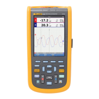
Do you have a question about the Fluke ScopeMeter 123B and is the answer not in the manual?
Provides telephone numbers for technical and calibration support.
General warnings and cautions for safe operation and product care.
Detailed list of items included in the Test Tool kit.
Instructions for charging and managing the Li-ion battery pack.
Steps to connect and use the mains power source.
Information on using the SD card for data storage.
Steps to restore the Test Tool to its default factory settings.
Adjusting screen brightness to optimize battery life.
Guide to navigating menus and functions using keypad buttons.
Details on Input A, Input B, and COM ports.
Procedures for configuring different measurement probes.
Utilizing the tilt stand and optional hanger accessory.
Steps to change the language preference on the Test Tool.
Critical safety precautions for operating in this mode.
Identifying and understanding parts of the Test Tool screen.
Hands-off signal optimization for stable display.
Understanding numeric readings and setup illustrations.
Procedures for voltage, R, C, D, continuity.
Setting up current, temp, and power measurements.
Automatic signal analysis and display optimization.
Freezing the current screen display.
Capturing and holding a stable measurement result.
Adjusting auto/manual range, screen graphics, and waveform position.
Adjusting waveform amplitude and time base.
Applying a filter to reduce high-frequency noise.
Controlling the visibility of waveform glitches.
Smoothing readings for improved stability.
Recording and viewing min/max variations over time.
Capturing single events with a one-time screen update.
Observing AC signals superimposed on DC.
Configuring trigger source, edge, and conditions.
Measuring amplitude, high/low values, and overshoot.
Adapting voltage readout and adjusting 10:1 probes.
Steps to enter and configure the mode.
Simultaneous display of voltage and current signals.
Analyzing voltage harmonics on Input A.
Analyzing current harmonics on Input B.
Calculating power harmonics from voltage/current.
Vertically zooming harmonic bar graphs for detail.
Using the tool for various fieldbus protocols.
Understanding signal properties and indicators.
Viewing the bus voltage waveform eye pattern.
Setting parameters for meter recording.
Differentiating between meter and scope recording functions.
Identifying and navigating recorded events.
Viewing and zooming logged meter data.
Jumping between specific recorded events.
Loading previously saved instrument configurations.
Copying, moving, renaming, and deleting saved data.
Connecting the tool to a PC via optical cable.
Connecting the tool via WiFi USB adapter.
Instructions for cleaning and storing the Test Tool.
Safety warnings and procedures for battery replacement.
Detailed steps for physically replacing the battery pack.
Adjusting 10:1 probes for optimal waveform response.
Tips to extend battery operational time.
Setting automatic shutdown times.
Customizing Autoset for slow waveforms or coupling.
Best practices for proper electrical grounding.
Details on frequency response and input impedance.
Specs for sensitivity, bandwidth limiter, and display modes.
Maximum voltage limits for inputs A and B.
Scope modes, ranges, sampling rate, time base.
Trigger settings and advanced scope functions.
Accuracy and details for the dual input meter.
DC voltage measurement ranges and accuracy.
AC/DC voltage measurement ranges and accuracy.
Peak measurement modes, ranges, and accuracy.
Frequency measurement ranges and accuracy.
Accuracy for various functions, pulse measurements.
Current measurement ranges, scale factors, and accuracy.
Temperature measurement specifications.
Decibel measurement specifications.
Crest factor measurement specifications.
Phase measurement modes, range, and accuracy.
Power quality measurements for the 125B model.
Pulse width modulated signal measurements.
Resistance measurement ranges and accuracy.
Continuity test parameters.
Diode test parameters.
Capacitance measurement ranges and accuracy.
Zero Set, AutoHold, settling times.
Details on cursor measurements on graphs.
Accuracy for rise and fall time measurements.
Details on meter and waveform recording.
Display type, resolution, waveform display.
Power adapter, battery, operating time.
Internal memory and SD card capacity.
Physical size and weight of the instrument.
USB and WiFi adapter interface details.
Operating environment, humidity, and altitude limits.
Electromagnetic compatibility and physical stress ratings.
Wireless adapter frequency range and output power.
Compliance with IEC safety standards.
Graphical representation of voltage limits against frequency.
Voltage handling precautions relative to earth ground.
| Category | Measuring Instruments |
|---|---|
| Model | 123B |
| Brand | Fluke |
| Type | ScopeMeter |
| Bandwidth | 20 MHz |
| Sample Rate | 100 MS/s |
| Input Channels | 2 |
| Display | Color LCD |
| Safety Rating | CAT III 600 V |
| Display Resolution | 320 x 240 pixels |
| Warranty | 3 Years |
| Battery Life | 7 hours |
| Input Impedance | 1 MΩ |
| Memory | Internal |
| Voltage Range | 600 V |
| Weight | 1.5 kg |
| Dimensions | 50 mm |


