EasyManua.ls Logo

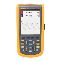
Fluke ScopeMeter 196C User Manual

Fluke ScopeMeter 196C
86 pages
To Next Page IconTo Next Page
Page #1 background imageLoading...
Page #1 background image
Fluke 19xB-19xC-2x5C
ScopeMeter
models 192B,196B,199B,192C,196C,199C,215C,225C
Service Manual
PN 4822 872 05391
September 2002, rev.2, Oct.09
© 2002-2009 Fluke Corporation, All rights reserved.
All product names are trademarks of their respective companies.

Table of Contents

Question and Answer IconNeed help?

Do you have a question about the Fluke ScopeMeter 196C and is the answer not in the manual?

Fluke ScopeMeter 196C Specifications

General IconGeneral
BrandFluke
ModelScopeMeter 196C
CategoryMeasuring Instruments
LanguageEnglish

Summary

Placing Orders and Getting Assistance

Safety Instructions

1.1 Introduction

Overview of safety information and warnings for safe operation.

1.2 Safety Precautions

General safety procedures for correct and safe use of the test tool.

1.3 Caution and Warning Statements

Explains the meaning of 'Caution' and 'Warning' statements.

1.4 Symbols

Lists and explains symbols used on the test tool and in manuals.

1.5 Impaired Safety

Procedures for handling the test tool when safety may be impaired.

1.6 General Safety Information

General safety information regarding internal parts and replacement parts.

Characteristics

List of Replaceable Parts

3.1 Introduction

Introduces the chapter listing replaceable parts by assembly and item number.

3.2 How to Obtain Parts

Instructions on how to contact service centers and order correct parts.

3.3 Final Assembly Parts

Lists final assembly parts and their ordering codes with item numbers.

3.4 Main PCA Unit Parts

Lists main PCA unit parts and their ordering codes with item numbers.

3.5 Accessories

Details standard and optional accessories with their ordering codes.

Performance Verification

4.1 Introduction

Introduces performance tests to ensure proper operating condition.

4.2 Equipment Required For Verification

Lists all necessary equipment and calibrators for performance tests.

4.3 General Instructions

General instructions to follow for all performance verification tests.

4.4 Operating Instructions

Instructions on resetting the tool and navigating menus for testing.

4.5 Display and Backlight Test

Procedure to test the display and backlight functionality of the tool.

4.6 Scope Input A&B Tests

Detailed tests for oscilloscope input A & B accuracy and functionality.

4.7 External Trigger Level Test

Procedure to test the external trigger level functionality.

4.8 Meter (DMM) Tests

Tests for the built-in multimeter (DMM) functions and accuracy.

4.9 Probe Calibration Generator Test

Test to verify the internal probe calibration square wave generator.

Calibration Adjustment

5.1 General

Provides an overview of the calibration adjustment procedure and its purpose.

5.2 Calibration Procedure Steps

Lists the sequential steps required for a complete calibration adjustment.

5.3 Starting the Calibration

Steps to enter the calibration mode and adjust the test tool date.

5.4 Contrast Calibration Adjustment

Procedure to adjust display darkness, default contrast, and brightness.

5.5 Warming Up & Pre-Calibration

The mandatory warming-up and pre-calibration steps before final adjustments.

5.6 Final Calibration

Detailed steps for final calibration adjustments, requiring specific inputs.

5.7 Save Calibration Data and Exit

Procedure to save calibration data and exit the maintenance mode.

5.8 Probe Calibration

Procedure to adjust voltage probes for optimal response and accuracy.

Disassembling the Test Tool

6.1 Introduction

Introduces procedures for disassembling the test tool safely.

6.2 Disassembly & Reassembly Procedures

Detailed steps for disassembling and reassembling the test tool components.

Related product manuals