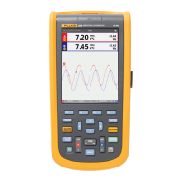
Do you have a question about the Fluke ScopeMeter 124B and is the answer not in the manual?
Identifies hazardous conditions and procedures that are dangerous to the user.
Describes the Li-ion battery, charging, and status indicators.
Explains how to use the mains power source to power the Test Tool.
Details the use of SD memory cards for data storage and warnings.
Procedure to restore the Test Tool to factory default settings.
Instructions on how to adjust display brightness to extend battery life.
Explains keypad navigation and basic sequence for adjusting parameters.
Details the input connections (A, B, COM) for measurements and grounding.
Guide on how to set up specific measurement probe types.
Explains the different areas of the screen and their functions.
Describes the Auto Set function for hands-off signal display.
Guides for voltage, current, and power measurements using probes.
Using test leads for Ohm, continuity, diode, and capacitance tests.
Hands-off operation with automatic meter reading selection.
Adjusting measurement type, range, amplitude, time base, and position.
Applying noise reduction, glitch display, and waveform smoothing.
Recording and displaying the minimum/maximum of live waveforms.
Procedure for performing a single-shot capture of events.
Using roll mode for low frequency signals and AC coupling.
Optimizing trigger level and slope for waveform acquisition.
Configuring trigger input, update, and slope for waveform display.
Using horizontal cursors to measure amplitude, high/low values, or overshoot.
Using vertical cursors to measure time difference and voltage difference.
Measuring rise time by setting cursors to specific trace heights.
Using VP41 10:1 probe for high frequency measurements.
Adapting the Test Tool's readout for probe attenuation and adjustment.
Simultaneously displays voltage and current for signal overview.
Explains the four columns of the Field Bus Test Screen.
Procedure to change test limits for selected bus types.
Steps to set parameters and start/stop meter recording.
Making precise digital measurements on plotted graphs in recorder mode.
Zooming logged data, navigating events, and scope record mode.
Setting up and recalling test sequences and settings.
Managing data sets: copy, move, rename, delete, and waveform comparison.
Connecting the Test Tool to a computer via optical interface.
Connecting the Test Tool to devices using a WiFi USB Adapter.
Basic cleaning instructions and recommendations for storing the Test Tool.
Battery replacement, 10:1 probe usage, and calibration information.
List of user-replaceable parts and optional accessories.
Tips for battery life conservation and power off timer settings.
Autoset options and guidelines for proper grounding.
Vertical specs, trigger, scope functions, and dual input meter accuracy.
Ohm, current, continuity, diode, and capacitance specs, plus meter functions.
Display, power, memory, interface, environmental, and EMC specs.
| Brand | Fluke |
|---|---|
| Model | ScopeMeter 124B |
| Category | Measuring Instruments |
| Language | English |


 Loading...