Do you have a question about the Fluke T90 and is the answer not in the manual?
Guides on proper tester holding and performing built-in self-tests.
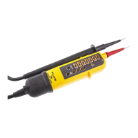
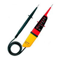
The Fluke T90/T110/T130/T150 are a series of voltage and continuity testers, with the T110, T130, and T150 models also featuring a rotary field indication. These devices are primarily designed for test and measurement applications in industrial, commercial, and household environments. They adhere to the latest safety standards, ensuring safe and reliable operation. A fixed test probe cover is integrated to mitigate the risk of injury when handling the instrument.
The core function of these testers is voltage measurement. The T90 and T110 models provide an LED bargraph to indicate nominal voltage levels, while the T130 and T150 models additionally display the measured voltage value on an LCD. The testers automatically activate when a voltage above 12 V is detected (or 6 V for the LCD on T130/T150 models). The LED bargraph and an independent ELV (Extra-Low Voltage) indicator LED (indicating >50 V AC / 120 V DC) are crucial for safety, especially when validating a zero voltage. For AC voltages, an AC symbol illuminates on the LCD (T130/T150), while for DC voltages, the polarity is indicated by '+' or '-' symbols on the LCD or corresponding LEDs. The ELV indicator is particularly important as it functions even in the absence of battery power or a main circuit failure.
The T150 model extends functionality to include resistance measurement, allowing for the testing of low ohm resistances between 1 Ω and 1999 Ω with a resolution of 1 Ω. This test should only be performed after ensuring the Unit Under Test (UUT) is not live.
Continuity and diode testing are also supported across the series. When performing a continuity test on cables, switches, relays, bulbs, or fuses, the tester will beep (if active) and illuminate a continuity symbol. For diode testing, the non-indicator test probe provides a positive (+) voltage, and the indicator test probe provides a negative (-) voltage.
The T110, T130, and T150 models incorporate a rotary field indication function, which is a double-pole system. This feature operates without a touch electrode and is usable even when wearing gloves, as the third pole is capacitively-coupled from the user's hand. It displays the voltage and the rotary field direction in a three-phase system, indicating whether the supposed phase L1 is the actual phase L1 and L2 is the actual phase L2 for right or left rotary fields.
For voltage tests, the T110, T130, and T150 models offer a "Switched Load" function, also known as an RCD Trip Test. This allows for a decrease in interference voltages from inductive or capacitive coupling by loading the UUT with a lower impedance. When testing RCD circuit breakers, pushing both buttons simultaneously can trip a 10 mA or 30 mA RCD in a 230 V system between L and PE. During this load current, the indicator probe vibrates, and an LED indicates the flowing load current.
The testers are designed for ease of use with pushbuttons controlling various functions. A "HOLD" function on the T130 and T150 models allows users to freeze the displayed voltage or resistance value on the LCD. This function automatically turns off after 30 seconds to conserve battery power.
The T110, T130, and T150 models include a torch light and backlight function, which is useful in poorly lit environments such as division switch cabinets. This function also automatically turns off after 30 seconds.
A beeper is integrated into the T110, T130, and T150 models for continuity, AC voltage, and single-pole phase test modes. The beeper can be toggled on or off by holding a specific button for 2 seconds, and its status is displayed on the LED or LCD. The beeper mode is stored until changed, and users are advised to perform a continuity test to ensure it's operational, especially in noisy environments.
The testers come with several accessories for enhanced usability and safety. These include a GS38 Probe Tip Sheath, 4 mm Probe Extensions, and a Probe Tip Protector Cap for secure storage. The cap also features an earth-pin safety-socket opener for UK sockets, which helps release safety covers.
Regular self-tests are crucial for ensuring the proper functioning of the tester. Users should perform a self-test before and after each use. This involves touching the probe tips together to check for continuity and beeper operation, verifying battery status, and then separating the probes to ensure all LEDs and LCD symbols illuminate for a brief period, confirming internal circuit integrity. Finally, measuring a known voltage (e.g., a 230 V socket outlet) completes the self-test, including the ELV circuit. If the tester fails any part of the self-test or voltage test, it should not be used and should be serviced.
Battery replacement is indicated by a low battery symbol on the T90/T110 models or a '+' symbol on the T130/T150 LCD. To replace batteries, the tester must be disconnected from any measurement circuit, the battery cover opened, and two new 1.5V IEC LR03 AAA batteries inserted with correct polarity. After replacement, the battery cover should be closed and a self-test performed.
For cleaning, the tester should be removed from all measurement circuits. It can be cleaned with a moist cloth and a weak detergent. Abrasives or solvents should not be used. After cleaning, the tester should not be used for 5 hours. Fluke recommends a calibration interval of 1 year to maintain accuracy.
To prevent battery leakage and damage, batteries should be removed if the product is not used for an extended period or stored outside its operating temperature range. Any repairs beyond battery replacement should be performed by an approved technician. Users are advised to keep the tester dry and clean and to avoid operating it with covers removed or the case open due to the risk of hazardous voltage exposure.
| Display type | - |
|---|---|
| Housing color | Black, Grey, Red, Yellow |
| AC current range | - A |
| AC voltage range | - V |
| Battery type | AAA |
| Number of batteries supported | 2 |
| Depth | 38 mm |
|---|---|
| Width | 70 mm |
| Height | 260 mm |
| Weight | 280 g |