16
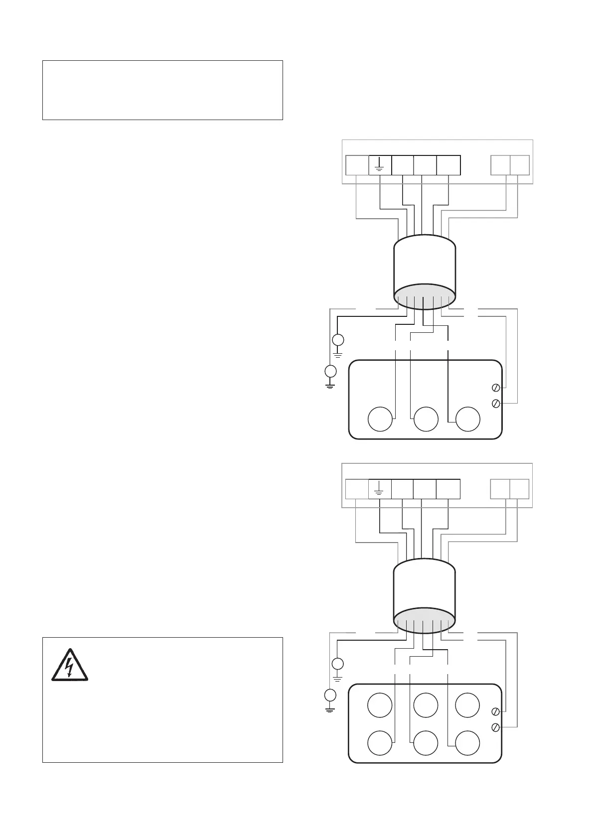
Y - Connection
4650 - 4660
CABLE
GC
GC
T1
T2
L2 L3 T1 T2L1
GC
3~
V1 W1
T2
U1
L1 L2L3
T1
NOTE! With long cables, the voltage drop must
be taken into consideration, since the motor’s
rated voltage is the voltage measured at the
terminal board in the machine.
Connection of the motor cable and
the stator leads
Connect the motor cble and stator leads as shown in
the wiring diagrams.
Cable
Conductors Connection Connection
starter terminal board
SUBCAB
®
4Gx
Brown L1 U1
Blue L2 W1
Black L3 V1
Yellow/Green Earth Earth
Black T1 T1* T1*
Black T2 T2* T2*
SUBCAB
®
xAWG/7
Red L1 U1
White L2 W1
Black L3 V1
Yellow GC** GC**
Yellow/Green Earth Earth
Orange T1* T1*
Blue T2* T2*
HCR SO7E6E5-7
Black 1 L1 U1
Black 2 L2 W1
Black 3 L3 V1
Black 4 T1* T1*
Black 5 T2* T2*
Black 6 - -
Yellow/Green Earth Earth
* Terminal for connection of termal contacts in motor and
monitoring equipment.
** GC = Ground Check
For safety reasons, the earth lead
should be longer than the phase
leads. If the motor cable is jerked
loose by mistake the earth lead
should be the last to come loose
from its terminal. This applies to both
ends of the cable.
Make sure that the mixer is
correctly earthed (grounded).
Stator leads
Stator leads Connection
terminal board
Red U1
Brown V1
Yellow W1
Y - Connection
4630 - 4640
CABLE
GC
GC
T1
T2
L2 L3 T1 T2L1
GC
3~
V1 W1
T2
U1
L1 L2L3
T1
Direct on line start
Direct on line start
If the direction of rotation is wrong, transpose two of
the phase leads.