13
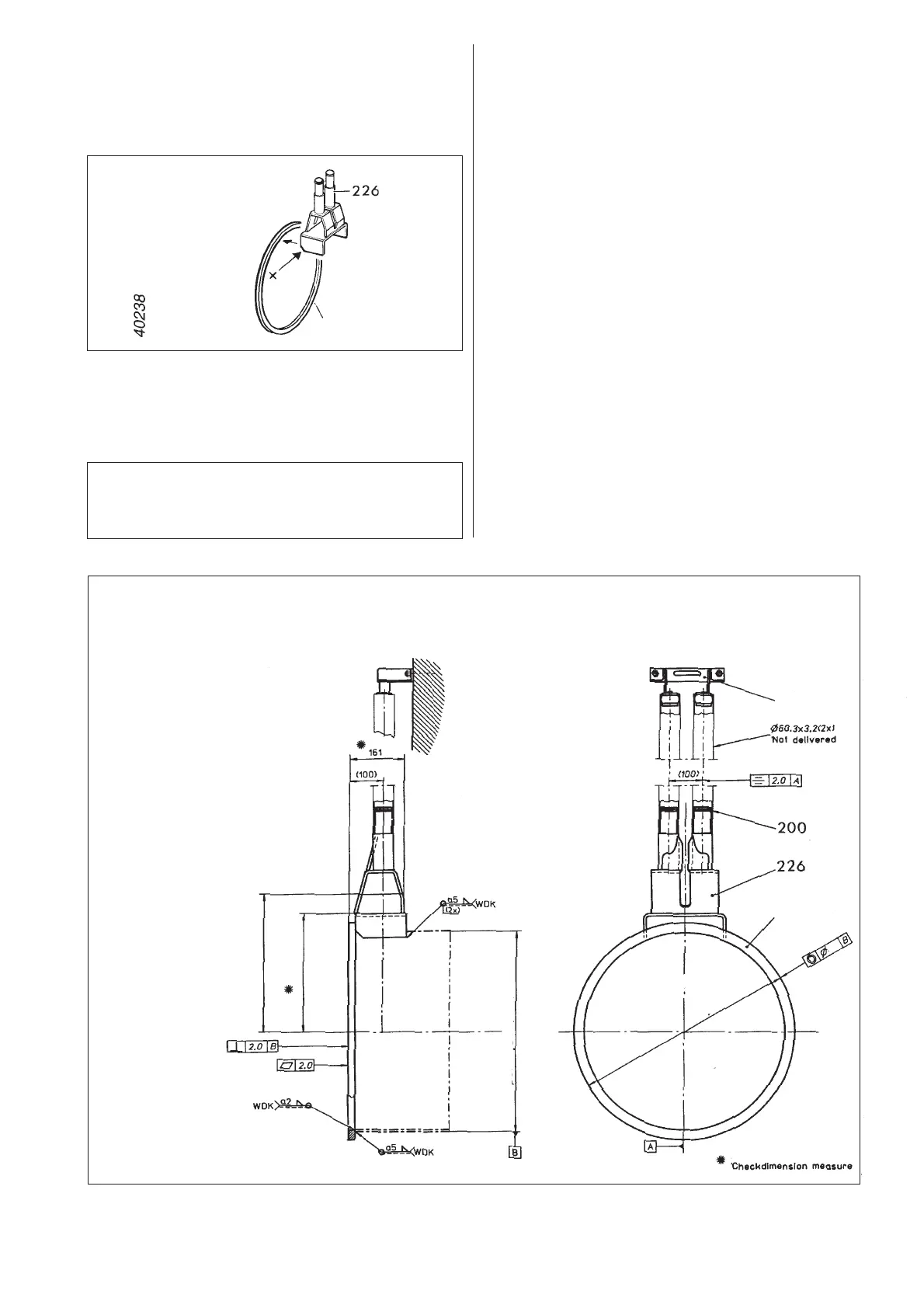
PP-pump installation
Mark out the location of the discharge connection on
the wall.
Drill a hole in the wall (a little wider than the diameter
of the tubes).
Weld together the bracket (226) and the ring (225).
NOTE! Place the bracket with the sloping (x) towards
the ring.
Centre the ring to the tube and weld the ring and
bracket together with the tube.
NOTE!
All welded joints must be pickled and polished
before they come into contact with the liquid.
The tube must have a diameter A and a wall diameter B.
4630, 4640 A 406.4 mm (16") B 6.3 mm (0.25")
4650, 4660 A 609.6 mm (24") B 6.3 mm (0.25")
4670, 4680 A 812.8 mm (32") B 8.0 mm (0.31")
NOTE! It is important that the ring is welded perpen-
dicular to the tube.
Place the unit in the wall.
Carefully measure the correct guide bar length. Cut
the bars to the right length. The guide bars must have
a diameter of 60.3 mm (2.37") and a wall thickness of
3.2 mm (0.13").
Place the guide bars on the bracket, don´t forget the
O-rings (200).
Put the guide holder unit (227) on the guide bars and
mark the location of the guide holder on the wall.
Drill holes and tap in expansion bolts. Place the guide
holder and guide bars in position, tighten the bolts.
Measure the centre-to-centre distance between the
guide bars, which should be 100 mm.
It is important that the guide bars are mounted
vertical, use a plumb line.
Tighten around the tube and check that the discharge
connection will be fixed in the wall.
4630, 4640
AB Ø 406 (DIN2458 Ø 406.4 x 6.3)
C Ø 460
D3.0
E 299
F 240
4650, 4660
AB Ø 610 (DIN2458 Ø 609.6 x 6.3)
C Ø 660
D4.0
E 417
F 358
4670, 4680
AB Ø 813 (DIN2458 Ø 812.8 x 8.0)
C Ø 870
D4.0
E 521
F 462
40279
E
F
Ø C
D
Ø AB
225
227
225