www.fmiproducts.com
56131J18
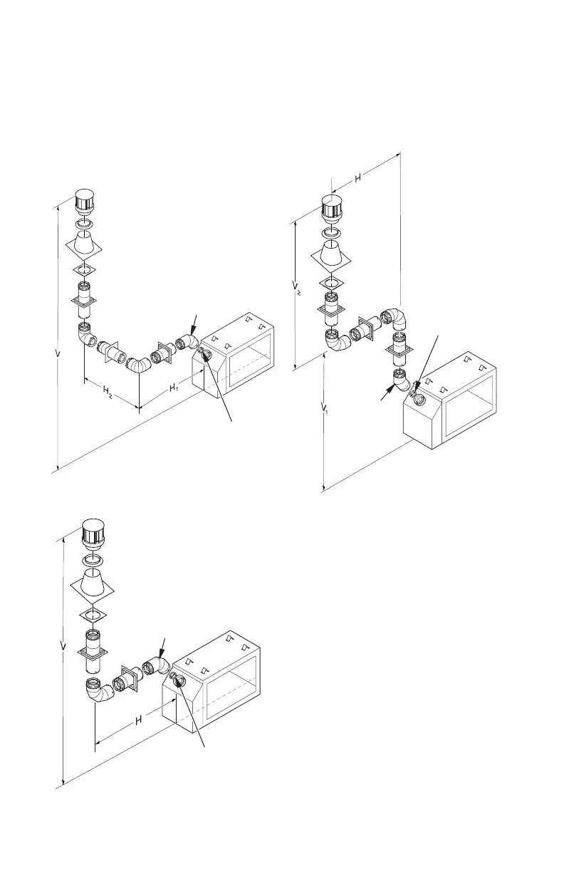
Vertical (V) Horizontal (H
1
) +
Horizontal (H
2
)
5' min. 2' max.
6' min. 4' max.
7' min. 6' max.
8' min. 8' max.
20' max. 8' max.
Figure 29 - Vertical Rigid Venting
Conguration Using Two 90° Elbows
with Two Horizontal Runs
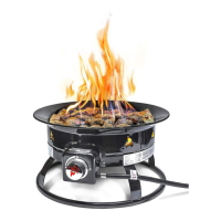
Vertical (V) Horizontal (H)
5' min. 2' max.
6' min. 4' max.
7' min. 6' max.
8' min. 8' max.
20' max. 8' max.
Figure 30 - Vertical Rigid Venting
Conguration Using One 90° Elbow
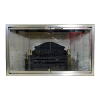
Vertical (V
1
) Horizontal (H)
5' min. 6' max.
6' min. 12' max.
7' min. 18' max.
8' min. 20' max.
Figure 31 - Vertical Rigid Venting
Conguration Using Two 90° Elbows
VENTING INSTALLATION
Continued
Figures 29 through 32 show four different
congurations for vertical termination. These
minimum vertical rises are based on horizon-
tal runs with a minimum of 1/4" upwards pitch
per foot and do not reect constraints on a
vertical system with 45° or greater offset.
45° Starter Elbow
Note: Install restrictor
into inner collar of
replace as shown.
45° Starter Elbow
Note: Install restrictor
into inner collar of
replace as shown.
45° Starter
Elbow
Note: Install restrictor
into inner collar of
replace as shown.
Any offset pitch of 45° or less must be
considered horizontal and sized within the
maximum allowable lengths listed in the fol-
lowing examples.