www.fmiproducts.com
56131J 23
O
F
F
P
I
L
O
T
O
N
L
O
H
I
P
I
L
O
T
EA
16AI
7
TPTH TP TH
Gas
Valve
To Thermopoile
Extension
Cord
Outlet Box
White
Red
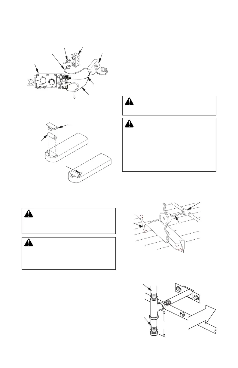
Figure 40 - Installing Remote Receiver
(SKYTECH Model)
Optional Fan
Kit Plug
Receiver
Pull to Remove
Insulation Tab
Battery
Cover
12 Volt
Battery
Figure 41 - Installing Battery in Hand-
Held Remote Control Unit (SKYTECH)
-
An equipment shutoff valve has been included
in the appliance’s gas supply system. You
may consider installing an extra gas shutoff
valve outside appliance’s enclosure (check
with local codes) where it can be accessed
more conveniently with a key through a wall
as shown in Figure 42.
Route a 1/2" NPT black iron gas line towards
appliance coming in from the left. It is recom-
mended to route pipe between stand of rebox
and surround of replace (see Figure 43).
FIREPLACE INSTALLATION
Continued
IMPORTANT: The appliance and its individual
shutoff valve must be disconnected from the
gas supply piping system during any pressure
testing of that system at test pressures in
excess of 1/2 psig. (3.5 kPa). The appliance
must be isolated from the gas supply piping
system by closing its individual equipment
shutoff valve during any pressure testing of
the gas supply piping system at test pressures
equal to or less than 1/2 psig. (3.5 kPa).
-
1. Install a sediment trap between incoming
gas line and gas control valve (see Figure
43). The sediment trap should extend
down center of pipe. Refer to your local
codes.
3" Min.
Side Wall
Of Appliance
Incoming 1/2" Gas
Line Permitted by
Local Codes
Figure 43 - Sediment Trap
Sediment
Trap (Not
Supplied)
Figure 42 - Typical Exterior Wall Gas
Shutoff Installation
Key
Extension
Shutoff
Valve