www.fmiproducts.com
56131J 25
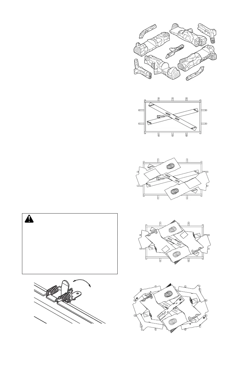
4. Figure 47 shows log set. Logs “A” have
the knot at end of log. Logs “B” have the
knot at middle of log. Twigs “C” have the
shape of a “Y”. Twigs “D” have the shape
of bent twigs. Twig “E” is a straight twig
which is placed across top of logs “B”.
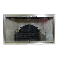
5. Figure 48 shows the top view of burner
and grate.
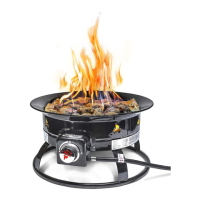
6. Place logs “A” as shown in Figure 49.
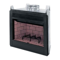
7. Place logs “B” as shown in Figure 50. Lift
end of log “A” that will be propped up and
place log “B” under it. At the same time,
the other side of log “B” is placed over
the other log “A”. Repeat procedure for
the other log “B”.
8. Take twigs “C” (shaped like a “Y”) and
place them as shown in Figure 51.
9. Take twigs “D” (bent twig) and place them
as shown in Figure 51.
10. Place twig “E” across top of logs “B” a
shown in Figure 51.
11. When nished installing logs, close glass
door. Make certain safety door switch is
fully pressed by door frame before secur-
ing four (4) spring loaded latches.
12. Replace louvers in reverse order with
grilles pointing in the down position.
-
-
vice, or maintenance can cause
additional information, consult
Figure 46 - Opening Door Latches
Figure 47 - Log Set (9 Pieces)
A
A
B
B
C
C
D
D
E
Figure 48 - Burner and Grate (Top View)
Figure 49 - Installing Logs “A” (Top View)
Figure 50 - Installing Logs “B ” (Top View)
Figure 51 - Installing Twigs “C, D, E ”
(Top View)
FIREPLACE
INSTALLATION
Continued